NCP803SN160T1G ON Semiconductor, NCP803SN160T1G Datasheet
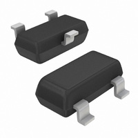
IC MPU RESET MONITOR 1.60V SOT23

NCP803SN160T1G

Manufacturer Part Number
NCP803SN160T1G
Description
IC MPU RESET MONITOR 1.60V SOT23
Manufacturer
ON Semiconductor
Type
Simple Reset/Power-On Resetr
Datasheets

Specifications of NCP803SN160T1G

Number Of Voltages Monitored
1
Output
Open Drain or Open Collector
Reset
Active Low
Reset Timeout
140 ms Minimum
Voltage - Threshold
1.6V
Operating Temperature
-40°C ~ 105°C
Mounting Type
Surface Mount
Package / Case
SOT-23-3, TO-236-3, Micro3™, SSD3, SST3
Monitored Voltage
1.2 V to 4.9 V
Undervoltage Threshold
1.6 V
Output Type
Open Collector / Drain
Manual Reset
Not Resettable
Watchdog
No Watchdog
Battery Backup Switching
No Backup
Supply Voltage (max)
5.5 V
Supply Voltage (min)
1 V
Supply Current (typ)
0.8 uA
Maximum Operating Temperature
+ 105 C
Mounting Style
SMD/SMT
Minimum Operating Temperature
- 40 C
Power Fail Detection
No
Number Of Elements
1
Monitored Voltage 1 (typ)
1.2 to 4.9V
Threshold Voltage 1 (max)
1.62V
Watchdog Timer
No
Chip Enable Signals
No
Reset Active Time
460ms
Package Type
SOT-23
Operating Supply Voltage (min)
1.2V
Operating Supply Voltage (max)
5.5V
Reset Threshold Voltage (max)
1.62V
Reset Threshold Voltage (min)
1.58V
Family Name
NCP803
Operating Temp Range
-40C to 105C
Operating Temperature Classification
Industrial
Mounting
Surface Mount
Pin Count
3
Supply Current
0.0008mA
Overvoltage Threshold
1.62 V
Power-up Reset Delay (typ)
460 ms
Lead Free Status / RoHS Status
Lead free / RoHS Compliant
Other names
NCP803SN160T1GOS
NCP803SN160T1GOS
NCP803SN160T1GOSTR

Available stocks

Company
Part Number
Manufacturer
Quantity
Price
Part Number:
NCP803SN160T1G
Manufacturer:
ON Semiconductor
Quantity:
500
Part Number:
NCP803SN160T1G
0
MAX803 Series,
NCP803 Series
Very Low Supply Current
3-Pin Microprocessor
Reset Monitor
designed to monitor V
the host processor when necessary. No external components are
required.
through the reset voltage threshold. Reset is maintained active for a
timeout period which is trimmed by the factory after V
the reset threshold. The MAX803/NCP803 has an open drain
active−low RESET output. Both devices are available in SOT−23 and
SC−70 packages.
on the V
these devices suitable for battery powered applications.
Features
Typical Applications
© Semiconductor Components Industries, LLC, 2009
February, 2009 − Rev. 6
The MAX803/NCP803 is a cost−effective system supervisor circuit
The reset output is driven active within 10 msec of V
The MAX803/NCP803 is optimized to reject fast transient glitches
Supplies
in 100 mV Steps
(1 ms, 20 ms, 100 ms, and 140 ms)
Precision V
Precision Monitoring Voltages from 1.2 V to 4.9 V Available
Four Guaranteed Minimum Power−On Reset Pulse Width Available
RESET Output Guaranteed to V
Low Supply Current
V
No External Components
Wide Operating Temperature: −40°C to 105°C
Pb−Free Packages are Available
Computers
Embedded Systems
Battery Powered Equipment
Critical Microprocessor Power Supply Monitoring
V
CC
CC
Transient Immunity
CC
line. Low supply current of 0.5 mA (V
CC
C = 100 nF
Figure 1. Typical Application Diagram
Monitor for 1.5 V, 2.5 V, 3.0 V, 3.3 V, and 5.0 V
CC
in digital systems and provide a reset signal to
MAX803
NCP803
GND
V
RESET
CC
CC
0
= 1.0 V
R
pull−up
CC
= 3.2 V) make
RESET
CC
rises above
GND
CC
V
mP
1
CC
falling
0
See detailed ordering and shipping information in the package
dimensions section on page 7 of this data sheet.
See general marking information in the device marking
section on page 7 of this data sheet.
1
(Note: Microdot may be in either location)
DEVICE MARKING INFORMATION
RESET
2
GND
xxx
M
G
ORDERING INFORMATION
3
PIN CONFIGURATION
http://onsemi.com
1
2
SOT−23/SC−70
= Specific Device Code
= Date Code
= Pb−Free Package
(SOT−323)
CASE 318
CASE 419
(TO−236)
SOT−23
SC−70
(Top View)
Publication Order Number:
3
1
1
MARKING
DIAGRAM
V
CC
xxx MG
3
xx MG
MAX803/D
G
G
2

Related parts for NCP803SN160T1G

NCP803SN160T1G Summary of contents

Page 1

MAX803 Series, NCP803 Series Very Low Supply Current 3-Pin Microprocessor Reset Monitor The MAX803/NCP803 is a cost−effective system supervisor circuit designed to monitor V in digital systems and provide a reset signal to CC the host processor when necessary. No ...

Page 2

V CC Vref 1 GND Figure 2. NCP803, MAX803 Series Open−Drain Active−Low Output PIN DESCRIPTION Pin No. Symbol Á Á Á Á Á Á Á Á Á Á Á Á Á Á Á Á Á Á Á Á Á ...

Page 3

... A 4. Contact your ON Semiconductor sales representative for other threshold voltage options. 5. Contact your ON Semiconductor sales representative for timeout options availability for other threshold voltage options −40°C to +105°C unless otherwise noted. Typical values are at T ...

Page 4

TYPICAL OPERATING CHARACTERISTICS 0 1 0.6 0.5 0.4 0.3 0.2 0.1 0 0.5 1.5 2.5 3.5 SUPPLY VOLTAGE (V) Figure 3. Supply Current vs. Supply Voltage 0 2. 0.3 0.2 0.1 0 ...

Page 5

TYPICAL OPERATING CHARACTERISTICS 125 100 100 200 −50 − TEMPERATURE (°C) Figure 9. Power−Down Reset ...

Page 6

Detail Operation Description The MAX803, NCP803 series microprocessor reset supervisory circuits are designed to monitor the power supplies in digital systems and provide a reset signal to the processor without any external components. Figure 2 shows the timing diagram and ...

Page 7

V Transient Rejection CC The MAX803/NCP803 series provides accurate V monitoring and reset timing power−down, and brownout/sag conditions, and rejects negative−going transients (glitches) on the power supply line. Figure 13 shows the maximum transient duration vs. maximum negative excursion (overdrive) ...

Page 8

... ORDERING, MARKING AND THRESHOLD INFORMATION Vth* (V) Part Number NCP803SN160T1 1.60 NCP803SN160T1G 1.60 NCP803SN232T1 2.32 NCP803SN232T1G 2.32 NCP803SN263T1 2.63 NCP803SN263T1G 2.63 NCP803SN293T1 2.93 NCP803SN293T1G 2.93 NCP803SN308T1 3.08 NCP803SN308T1G 3.08 NCP803SN400T1G 4.00 NCP803SN438T1 4.38 NCP803SN438T1G 4.38 NCP803SN463T1 4.63 NCP803SN463T1G 4.63 NCP803SN120T1G 1.20 NCP803SN293D1T1G 2 ...

Page 9

... *For additional information on our Pb−Free strategy and soldering details, please download the ON Semiconductor Soldering and Mounting Techniques Reference Manual, SOLDERRM/D. PACKAGE DIMENSIONS SOT−23 (TO236) CASE 318−08 ISSUE AN NOTES: 1. DIMENSIONING AND TOLERANCING PER ANSI Y14.5M, 1982. 2. CONTROLLING DIMENSION: INCH. 3. MAXIMUM LEAD THICKNESS INCLUDES LEAD FINISH THICKNESS ...

Page 10

... A1 *For additional information on our Pb−Free strategy and soldering details, please download the ON Semiconductor Soldering and Mounting Techniques Reference Manual, SOLDERRM/D. ON Semiconductor and are registered trademarks of Semiconductor Components Industries, LLC (SCILLC). SCILLC reserves the right to make changes without further notice to any products herein ...

Related keywords