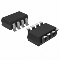
MAX6726KASYD3+T Maxim Integrated Products, MAX6726KASYD3+T Datasheet - Page 12

MAX6726KASYD3+T
Manufacturer Part Number
MAX6726KASYD3+T
Description
IC SUPERVISOR MPU SOT23-8
Manufacturer
Maxim Integrated Products
Type
Multi-Voltage Supervisorr
Datasheet
1.MAX6718UKSYD3T.pdf
(19 pages)
Specifications of MAX6726KASYD3+T
Number Of Voltages Monitored
3
Output
Push-Pull, Push-Pull
Reset
Active High/Active Low
Reset Timeout
140 ms Minimum
Voltage - Threshold
2.188V, 2.925V, Adj
Operating Temperature
-40°C ~ 85°C
Mounting Type
Surface Mount
Package / Case
SOT-23-8
Monitored Voltage
1.8 V to 5 V, 0.9 V to 3.3 V
Undervoltage Threshold
2.85 V, 2.125 V, Adjustable
Overvoltage Threshold
3 V, 2.25 V, Adjustable
Output Type
Active High, Active Low, Push-Pull
Manual Reset
Resettable
Watchdog
Watchdog
Battery Backup Switching
No Backup
Power-up Reset Delay (typ)
210 ms
Supply Voltage (max)
5.5 V
Supply Voltage (min)
0.8 V
Supply Current (typ)
15 uA
Maximum Power Dissipation
714 mW
Maximum Operating Temperature
+ 85 C
Mounting Style
SMD/SMT
Minimum Operating Temperature
- 40 C
Power Fail Detection
No
Lead Free Status / RoHS Status
Lead free / RoHS Compliant
These µP supervisors can monitor either positive or
negative supplies using a resistor voltage-divider to
PFI. PFO can be used to generate an interrupt to the µP
or cause reset to assert (Figure 3).
The power-fail comparator can be used to monitor a
negative supply voltage using the circuit shown in
Figure 3. When the negative supply is valid, PFO is low.
When the negative supply voltage drops, PFO goes
high. The circuit’s accuracy is affected by the PFI
threshold tolerance, V
The MAX6715–MAX6729 supervisors are relatively
immune to short-duration negative-going V
(glitches). It is usually undesirable to reset the µP when
V
Operating Characteristics show Maximum Transient
Duration vs. Reset Threshold Overdrive, for which reset
pulses are not generated. The graph was produced
using negative-going V
and ending below the reset threshold by the magnitude
indicated (reset threshold overdrive). The graph shows
the maximum pulse width that a negative-going V
transient may typically have without causing a reset
pulse to be issued. As the amplitude of the transient
increases (i.e., goes farther below the reset threshold),
the maximum allowable pulse width decreases. A 0.1µF
bypass capacitor mounted close to the V
vides additional transient immunity.
Setting and resetting the watchdog input at different
points in the program, rather than “pulsing” the watch-
dog input high-low-high or low-high-low, helps the
Dual/Triple Ultra-Low-Voltage SOT23 µP
Supervisory Circuits
Figure 5. Adding Hysteresis to Power-Fail for Push-Pull PFO
12
CC
V
EXT
A
R1
R2
______________________________________________________________________________________
Monitoring an Additional Power Supply
experiences only small glitches. The Typical
PFI
Watchdog Software Considerations
MAX6728/
MAX6729
GND
Negative-Going V
R3
Monitoring a Negative Voltage
PFO
CC
V
V
V
R2 = 200kΩ (FOR > 2.5µA R2 CURRENT)
R1 = R2 ((V
R3 = (R1 x V
CC
GOOD
FAIL
OH
, R1, and R2.
PFO
V
= V
IN
= DESIRED V
= DESIRED V
CC
pulses, starting above V
1 (FOR PUSH-PULL PFO)
GOOD
OH
) / (V
- V
EXT
GOOD
EXT
PFI
FAIL VOLTAGE THRESHOLD
) - (V
GOOD VOLTAGE THRESHOLD
- V
CC
PFI
FAIL
)(V
)
GOOD
Transients
CC
V
V
GOOD
FAIL
CC
- V
FAIL
transients
) / V
pin pro-
OH
) / V
PFI
CC
TH
watchdog timer to closely monitor software execution.
This technique avoids a “stuck” loop where the watch-
dog timer continues to be reset within the loop, keeping
the watchdog from timing out. Figure 6 shows an exam-
ple flow diagram where the I/O driving the watchdog
input is set high at the beginning of the program, set low
at the beginning of every subroutine or loop, then set
high again when the program returns to the beginning. If
the program should “hang” in any subroutine, the I/O is
continually set low and the watchdog timer is allowed to
time out, causing a reset or interrupt to be issued.
TRANSISTOR COUNT: 1072
PROCESS: BiCMOS
Figure 6. Watchdog Flow Diagram
SUBROUTINE
COMPLETED
SUBROUTINE OR
PROGRAM LOOP
SET WDI LOW
PROGRAM
SET WDI
RETURN
START
CODE
HIGH
Chip Information
SUBROUTINE
HANG IN


