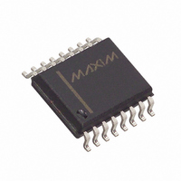
MAX1232EWE+T Maxim Integrated Products, MAX1232EWE+T Datasheet - Page 3

MAX1232EWE+T
Manufacturer Part Number
MAX1232EWE+T
Description
IC MPU MONITOR 16-SOIC
Manufacturer
Maxim Integrated Products
Type
Simple Reset/Power-On Resetr
Datasheet
1.MAX1232CSA.pdf
(6 pages)
Specifications of MAX1232EWE+T
Number Of Voltages Monitored
1
Output
Open Drain or Open Collector
Reset
Active High/Active Low
Reset Timeout
250 ms Minimum
Voltage - Threshold
4.37V, 4.62V
Operating Temperature
-40°C ~ 85°C
Mounting Type
Surface Mount
Package / Case
16-SOIC (0.300", 7.5mm Width)
Monitored Voltage
4.5 V, 4.75 V
Undervoltage Threshold
4.5 V, 4.25 V
Overvoltage Threshold
4.49 V, 4.74 V
Output Type
Active High, Active Low, Open Drain
Manual Reset
Resettable
Watchdog
Watchdog
Battery Backup Switching
No Backup
Power-up Reset Delay (typ)
1000 ms
Supply Voltage (max)
5.5 V
Supply Voltage (min)
4.5 V
Supply Current (typ)
200 uA
Maximum Operating Temperature
+ 85 C
Mounting Style
SMD/SMT
Minimum Operating Temperature
- 40 C
Power Fail Detection
No
Lead Free Status / RoHS Status
Lead free / RoHS Compliant
AC Electrical Characteristics
(V
Note 1: PBRST is internally pulled up to V
Note 2: Measured with outputs open.
Note 3: All voltages referenced to GND.
Note 4: Guaranteed by desing.
Note 5: PBRST must be held low for a minimum of 20ms to guarantee a reset.
Note 6: t
PBRST (Note 5)
PBRST Delay
Reset Active Time
ST Pulse Width
ST Timeout Period
V
V
V
Low
V
Open (Note 6)
1, 3, 5, 7, 10,
CC
CC
CC
CC
CC
WIDE SO
12, 14, 16
= +5V ±10%, T
Fall Time (Note 4)
Rise Time (Note 4)
Detect to RST High and RST
Detect to RST Low and RST
11
13
15
2
4
6
8
9
R
PARAMETER
= 5µs.
PIN
DIP/SO
A
_______________________________________________________________________________________
—
1
2
3
4
5
6
7
8
= T
MIN
to T
PBRST
NAME
MAX
GND
N.C.
TOL
V
RST
RST
TD
ST
CC
SYMBOL
)
t
t
t
t
t
PBD
t
BPD
BPU
RST
t
PB
TD
t
t
ST
B
F
CC
No Connection
Pushbutton Reset Input. A debounced active-low input that ignores pulses less than 1ms
in duration and is guaranteed to recognize inputs of 20ms or greater.
Time Delay Set. The watchdog timebase select input (t
Tolerance Input. Connect to GND for 5% tolerance or to V
Ground
Reset Output (Active High). Goes active:
(1) If VCC falls below the selected reset voltage threshold
(2) If PBRST is forced low
(3) If ST is not strobed within the minimum timeout period
(4) During power-up
Reset Output (Active Low, Open-Drain). See RST.
Strobe Input. Input for watchdog timer.
The +5V Power-Supply Input
600ms for TD = open, t
with an internal impedance of typically 40kΩ.
Figure 3
Figure 3
Figure 4
Figure 4, TD pin = 0V
TD pin = open
TD pin = V
Figure 5
Figure 6
Figure 7, V
Figure 8, V
CC
CC
CC
falling
rising
CONDITIONS
TD
Microprocessor Monitor
= 1.2s for TD = V
FUNCTION
CC
).
MIN
62.5
250
250
500
250
TD
20
75
10
1
0
CC
= 150ms for TD = 0V, t
for 10% tolerance.
Pin Description
1200
TYP
610
150
600
610
4
MAX
1000
1000
2000
1000
250
100
20
TD
UNITS
=
ms
ms
ms
ms
ms
ns
µs
µs
ns
3


