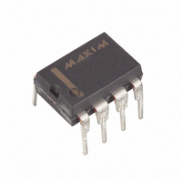
MAX703CPA Maxim Integrated Products, MAX703CPA Datasheet - Page 4

MAX703CPA
Manufacturer Part Number
MAX703CPA
Description
IC MPU SUPERVISORY CIRCUIT 8-DIP
Manufacturer
Maxim Integrated Products
Type
Battery Backup Circuitr
Datasheet
1.MAX703CSA.pdf
(9 pages)
Specifications of MAX703CPA
Number Of Voltages Monitored
1
Output
Push-Pull, Totem Pole
Reset
Active Low
Reset Timeout
140 ms Minimum
Voltage - Threshold
4.65V
Operating Temperature
0°C ~ 70°C
Mounting Type
Through Hole
Package / Case
8-DIP (0.300", 7.62mm)
Lead Free Status / RoHS Status
Contains lead / RoHS non-compliant
Available stocks
Company
Part Number
Manufacturer
Quantity
Price
Company:
Part Number:
MAX703CPA
Manufacturer:
MAXIM
Quantity:
5 510
Company:
Part Number:
MAX703CPA
Manufacturer:
MAXIM
Quantity:
5 510
Part Number:
MAX703CPA
Manufacturer:
MAXIM/美信
Quantity:
20 000
Company:
Part Number:
MAX703CPA+
Manufacturer:
Maxim
Quantity:
150
Company:
Part Number:
MAX703CPA/EPA
Manufacturer:
OMRON
Quantity:
5 510
Low-Cost Microprocessor Supervisory
Circuits with Battery Backup
Figure 1. Block Diagram
4
V
BATT
V
MR
PIN
PFI
CC
1
2
3
4
5
6
7
8
_______________________________________________________________________________________
RESET
NAME
V
V
GND
V
PFO
PFI
MR
BATT
OUT
CC
BATTERY-SWITCHOVER
1.25V
CIRCUITRY
Supply Output for CMOS RAM. When V
channel MOSFET switch. When V
+5V Supply Input
Ground
Power-Fail Comparator Input. When PFI is less than 1.25V, PFO goes low; otherwise PFO remains high. Connect
PFI to GND or V
P ow er - Fai l C om p ar ator O utp ut. It g oes l ow and si nks cur r ent w hen P FI i s l ess than 1.25V ; other w i se P FO r em ai ns hi g h.
Manual Reset Input. Generates a reset pulse when pulled below 0.8V. This active-low input is TTL/CMOS
compatible and can be shorted to ground with a switch. It has an internal 250µA pullup current. Leave floating
when not used.
Reset Output. Remains low while V
It remains low for 200ms after V
Backup-Battery Input. When V
greater than V
repeated switching if V
1.25V
GND
CC
CC
. When V
when not used.
MAX703
MAX704
CC
GENERATOR
CC
falls slowly.
RESET
rises 20mV above V
CC
CC
CC
falls below the reset threshold, V
CC
rises above the reset threshold (Figure 2) or MR goes from low to high.
is below the reset threshold, the higher of V
is below the reset threshold (4.65V for the MAX703, 4.40V for the MAX704).
CC
V
RESET
PFO
OUT
is above the reset threshold, V
BATT
FUNCTION
Figure 2. Timing Diagram
RESET
*PFO DEPENDS ON PFI EXCEPT IN BATTERY-BACKUP MODE, WHERE PFO IS LOW.
, V
V
PFO*
V
+5V
+5V
+5V
+5V
OUT
0V
0V
0V
CC
0V
CC
is switched to V
V
3.0V
RST
BATT
is switched to V
OUT
OUT
connects to V
. The 40mV hysteresis prevents
CC
or V
OUT
BATT
Pin Description
CC
if V
is connected to V
through a p-
BATT
t
RST
V
is 20mV
BATT
= 3.0V
OUT
.


