Operating Temperature ......................................... -45 °C to +85 °C
Maximum Device Surface Temperature
Passive Aging ....................................................... +85 °C, 1000 hours ............................................... ±2 % typical resistance change
Humidity Aging ..................................................... +85 °C, 85 % R.H. 500 hours ............................... ±3 % typical resistance change
Thermal Shock ..................................................... MIL-STD-202F, Method 107G, ............................. ±10 % typical resistance change
Solvent Resistance ............................................... MIL-STD-202, Method 215B ................................ No change
Lead Solerability ................................................... ANSI/J-STD-002
Flammability ......................................................... IEC 695-2-2 .......................................................... No Flame for 60 secs.
Vibration ............................................................... MIL-STD-883C, Method 2007.1, Condition A ...... No change
Test
Visual/Mech. .................................................... Verify dimensions and materials ...................... Per MF physical description
Resistance ....................................................... In still air @ 23 °C ............................................. Rmin ≤ R ≤ Rmax
Time to Trip ...................................................... At specifi ed current, Vmax, 23 °C ................... T ≤ max. time to trip (seconds)
Hold Current .................................................... 30 min. at Ihold ................................................ No trip
Trip Cycle Life .................................................. Vmax, Imax, 100 cycles ................................... No arcing or burning
Trip Endurance ................................................ Vmax, 48 hours ................................................ No arcing or burning
Solderability ..................................................... MIL-STD-202F, Method 208F .......................... 95 % min. coverage
UL File Number ............................................... E 174545S
CSA File Number ............................................. CA 110338
TÜV File Number ............................................. R2057213
MF-SM013/250-2
MF-SM013/250-A-2
MF-SM013/250-B-2
MF-SM013/250-C-2
MF-SM013/250-2
MF-SM013/250-A-2
MF-SM013/250-B-2
MF-SM013/250-C-2
Test Procedures And Requirements For Model MF-SM013/250 Series
Thermal Derating Chart - I hold/ I trip (Amps)
Electrical Characteristics
Environmental Characteristics
in Tripped State ................................................ 125 °C
.......................................................................... +125 °C to -55 °C,10 times .................................. ±15 % typical resistance change
Model
Model
0.21 / 0.42
0.21 / 0.42
0.21 / 0.42
0.21 / 0.42
-40 ºC
Operating
Voltage
Max.
Volts
(V)
60
60
60
60
0.18 / 0.37
0.18 / 0.37
0.18 / 0.37
0.18 / 0.37
-20 ºC
+60 °C, 1000 hours ............................................... ±3 % typical resistance change
Test Conditions
Features
■
■
■
■
■
■
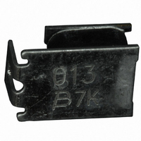
MF-SM013/250 - Telecom PTC Resettable Fuses
Volts
Max.
250
250
250
250
Max. Interrupt
(V)
0.16 / 0.31 0.13 / 0.26 0.10 / 0.23 0.09 / 0.18 0.08 / 0.15 0.07 / 0.12
0.16 / 0.31 0.13 / 0.26 0.10 / 0.23 0.09 / 0.18 0.08 / 0.15 0.07 / 0.12
0.16 / 0.31 0.13 / 0.26 0.10 / 0.23 0.09 / 0.18 0.08 / 0.15 0.07 / 0.12
0.16 / 0.31 0.13 / 0.26
Surface Mount Devices
High voltage surge capabilities
Binned and sorted resistance ranges
Assists in meeting ITU K.20/K.21
specifi cations
RoHS compliant*
Agency recognition:
Ratings
0 ºC
Amps
Max.
3.0
3.0
3.0
3.0
(A)
Ambient Operating Temperature
23 ºC
at 23 °C
Current
Amps
Hold
0.13
0.13
0.13
0.13
I H
0.10 / 0.23 0.09 / 0.18 0.08 / 0.15 0.07 / 0.12
Customers should verify actual device performance in their specifi c applications.
40 ºC
at 23 °C
Ohms
Min.
6.5
6.5
9.0
7.0
Resistance
Initial
Accept/Reject Criteria
50 ºC
*RoHS Directive 2002/95/EC Jan 27, 2003 including Annex.
Applications
Used as a secondary overcurrent protection
device in:
■
■
■
Ohms
at 23
Max.
12.0
12.0
10.0
9.0
Customer Premise Equipment (CPE)
Central Offi ce (CO)
Subscriber Line Interface Cards (SLIC)
°C
Specifi cations are subject to change without notice.
60 ºC
Resistance
One Hour
Post-Trip
at 23 °C
Ohms
Max.
20.0
20.0
20.0
20.0
70 ºC
Dissipation
at 23 °C
Tripped
Power
Watts
0.05 / 0.10
0.05 / 0.10
0.05 / 0.10
0.05 / 0.10
Typ.
3.3
3.3
3.3
3.3
85 ºC


