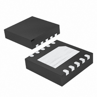
MAX16016LTBS+T Maxim Integrated Products, MAX16016LTBS+T Datasheet

MAX16016LTBS+T
Specifications of MAX16016LTBS+T
Related parts for MAX16016LTBS+T
MAX16016LTBS+T Summary of contents
Page 1
... GPS Systems Set-Top Boxes Point-of-Sale Equipment Portable/Battery Equipment registered trademark of Underwriters Laboratories, Inc. ________________________________________________________________ Maxim Integrated Products For pricing, delivery, and ordering information, please contact Maxim Direct at 1-888-629-4642, or visit Maxim’s website at www.maxim-ic.com. o System Monitoring for 5V, 3.3V, 3V, 2.5V, or 1.8V Power-Supply Voltages o 1.53V to 5.5V Operating Voltage Range o Low 1.2µ ...
Page 2
Low-Power µP Supervisory Circuits with Battery-Backup Circuit and Chip-Enable Gating ABSOLUTE MAXIMUM RATINGS V , BATT, OUT, BATT_TEST to GND.....................-0.3V to +6V CC RESET, RESET, PFO, BATTOK, WDO, BATTON, BATT_TEST, LL, (all open-drain) to GND .................-0.3V to +6V RESET, RESET, ...
Page 3
Low-Power µP Supervisory Circuits with Battery-Backup Circuit and Chip-Enable Gating ELECTRICAL CHARACTERISTICS (continued 1.53V to 5.5V 3V -40°C to +85°C, unless otherwise noted. Typical values are BATT A PARAMETER SYMBOL RESET ...
Page 4
Low-Power µP Supervisory Circuits with Battery-Backup Circuit and Chip-Enable Gating ELECTRICAL CHARACTERISTICS (continued 1.53V to 5.5V 3V -40°C to +85°C, unless otherwise noted. Typical values are BATT A PARAMETER SYMBOL WATCHDOG ...
Page 5
Low-Power µP Supervisory Circuits with Battery-Backup Circuit and Chip-Enable Gating ELECTRICAL CHARACTERISTICS (continued 1.53V to 5.5V 3V -40°C to +85°C, unless otherwise noted. Typical values are BATT A PARAMETER SYMBOL LOW ...
Page 6
Low-Power µP Supervisory Circuits with Battery-Backup Circuit and Chip-Enable Gating Table 2. Low-Line Threshold Ranges SUFFIX 5V 0V +25°C, unless otherwise noted.) CC BATT A ...
Page 7
Low-Power µP Supervisory Circuits with Battery-Backup Circuit and Chip-Enable Gating ( +25°C, unless otherwise noted.) CC BATT OUT ON-RESISTANCE CC vs. TEMPERATURE 3.15V 65mA CC ...
Page 8
Low-Power µP Supervisory Circuits with Battery-Backup Circuit and Chip-Enable Gating ( +25°C, unless otherwise noted.) CC BATT A WDO OUTPUT VOLTAGE LOW vs. SINK CURRENT 0.5 0.4 0 3.3V CC 0.2 ...
Page 9
Low-Power µP Supervisory Circuits with Battery-Backup Circuit and Chip-Enable Gating PIN NAME 1 V Supply Voltage Input. Bypass V CC Backup Battery Input BATT BATT CC capacitor. Active-Low Manual Reset Input. RESET asserts when MR ...
Page 10
Low-Power µP Supervisory Circuits with Battery-Backup Circuit and Chip-Enable Gating PIN NAME MAX16020 MAX16021 1 1 BATT PFI 4 4 WDI — BATT_TEST — 6 RESET 7 7 BATTOK 8 8 ...
Page 11
Low-Power µP Supervisory Circuits with Battery-Backup Circuit and Chip-Enable Gating Pin Description—MAX16020/MAX16021 (continued) PIN NAME MAX16020 MAX16021 WDO 9 9 PFO GND RESET OUT CEOUT 14 14 CEIN ...
Page 12
Low-Power µP Supervisory Circuits with Battery-Backup Circuit and Chip-Enable Gating BATTERY FRESHNESS SEAL PFI WDI 100nA 12 ______________________________________________________________________________________ BATT OUT REF CLEAR WATCHDOG WATCHDOG TRANSITION TIMER DETECTOR 25kΩ GND Functional Diagrams OUT BATTON RESET DELAY RESET PFO ...
Page 13
Low-Power µP Supervisory Circuits with Battery-Backup Circuit and Chip-Enable Gating BATTERY FRESHNESS SEAL PF1 WATCHDOG WDI TRANSITION DETECTOR 25kΩ CEIN 100nA MAX16020 MAX16021 ______________________________________________________________________________________ Functional Diagrams (continued) BATT OUT REF OUT CE OUTPUT CONTROL CLEAR WATCHDOG TIMER ...
Page 14
Low-Power µP Supervisory Circuits with Battery-Backup Circuit and Chip-Enable Gating Detailed Description The Typical Application Circuit shows a typical connec- tion using the MAX16020. OUT powers the static ran- dom-access memory (SRAM reset threshold ( ...
Page 15
Low-Power µP Supervisory Circuits with Battery-Backup Circuit and Chip-Enable Gating The watchdog monitors µP activity through the input WDI. If the µP becomes inactive, either the reset output is asserted in pulses (MAX16016) or the watchdog output goes low (MAX16020/MAX16021). ...
Page 16
Low-Power µP Supervisory Circuits with Battery-Backup Circuit and Chip-Enable Gating To reenable the freshness seal: 1) Connect a battery to BATT. 2) Bring Drive MR higher than V + 1.2V for at least 3µs. BATT ...
Page 17
Low-Power µP Supervisory Circuits with Battery-Backup Circuit and Chip-Enable Gating Adding Hysteresis to PFI The power-fail comparators have a typical input hys- teresis This is sufficient for most applica- PFT-HYS tions where a power-supply line is being ...
Page 18
Low-Power µP Supervisory Circuits with Battery-Backup Circuit and Chip-Enable Gating BATT V CC MAX16020L BATT_TEST Figure 6. Adjustable BATT_TEST Load 18 ______________________________________________________________________________________ When V is above removed without danger of triggering a reset pulse. The device does ...
Page 19
Low-Power µP Supervisory Circuits with Battery-Backup Circuit and Chip-Enable Gating TOP VIEW MAX16016 + TDFN SECONDARY 0.1µF DC VOLTAGE R1 PFI R2 PFO MR BATT 0.1µF ______________________________________________________________________________________ Pin Configurations (continued) BATT ...
Page 20
Low-Power µP Supervisory Circuits with Battery-Backup Circuit and Chip-Enable Gating ALL LOGIC PART OUTPUTS (EXCEPT BATT_TEST) MAX16016LTB_ Push-pull MAX16016PTB_ Open-drain MAX16020LTE_ Push-pull MAX16020PTE_ Open-drain MAX16021LTE_ Push-pull MAX16021PTE_ Open-drain Ordering Information (continued) PART TEMP RANGE MAX16020_TE_+T -40°C to +85°C MAX16021_TE_+T -40°C ...
Page 21
... Maxim cannot assume responsibility for use of any circuitry other than circuitry entirely embodied in a Maxim product. No circuit patent licenses are implied. Maxim reserves the right to change the circuitry and specifications without notice at any time. Maxim Integrated Products, 120 San Gabriel Drive, Sunnyvale, CA 94086 408-737-7600 ____________________ 21 © 2010 Maxim Integrated Products ...


