DS1231S-35 Maxim Integrated Products, DS1231S-35 Datasheet
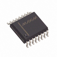
IC POWER MONITOR 35NS 16-SOIC

DS1231S-35

Manufacturer Part Number
DS1231S-35
Description
IC POWER MONITOR 35NS 16-SOIC
Manufacturer
Maxim Integrated Products
Type
Simple Reset/Power-On Resetr
Datasheet

Specifications of DS1231S-35

Number Of Voltages Monitored
1
Output
Open Drain or Open Collector
Reset
Active High/Active Low
Reset Timeout
150 ms Minimum
Voltage - Threshold
4.37V, 4.62V
Operating Temperature
0°C ~ 70°C
Mounting Type
Surface Mount
Package / Case
16-SOIC (0.300", 7.5mm Width)
Lead Free Status / RoHS Status
Contains lead / RoHS non-compliant
FEATURES
DESCRIPTION
The DS1231 Power Monitor Chip uses a precise tem-
perature-compensated reference circuit which provides
an orderly shutdown and an automatic restart of a pro-
cessor-based system. A signal warning of an impending
power failure is generated well before regulated DC
voltages go out of specification by monitoring high volt-
age inputs to the power supply regulators. If line isola-
tion is required a UL-approved opto-isolator can be di-
rectly interfaced to the DS1231. The time for processor
Warns processor of an impending power failure
Provides time for an orderly shutdown
Prevents processor from destroying nonvolatile
memory during power transients
Automatically restarts processor after power is
restored
Suitable for linear or switching power supplies
Adjusts to hold time of the power supply
Supplies necessary signals for processor interface
Accurate 5% or 10% V
Replaces power-up reset circuitry
No external capacitors required
Optional 16-pin SOIC surface mount package
CC
monitoring
PIN ASSIGNMENT
PIN DESCRIPTION
IN
MODE
TOL
GND
RST
RST
NMI
V
NC
shutdown is directly proportional to the available
hold-up time of the power supply. Just before the
hold-up time is exhausted, the Power Monitor uncondi-
tionally halts the processor to prevent spurious cycles
by enabling Reset as V
10 percent threshold. When power returns, the proces-
sor is held inactive until well after power conditions have
stabilized, safeguarding any nonvolatile memory in the
system from inadvertent data changes.
CC
MODE
MODE
GND
TOL
NC
NC
NC
GND
NC
IN
TOL
– Input
– Selects input pin characteristics
– Selects 5% or 10% V
– Ground
– Reset (Active High)
– Reset (Active Low, open drain)
– Non–Maskable Interrupt
– +5V Supply
– No Connections
IN
See Mech. Drawings
Power Monitor Chip
DS1231S 16–Pin SOIC
DS1231 8–Pin DIP
See Mech. Drawings
1
2
3
4
(300 MIL)
Section
1
2
3
4
5
6
7
8
CC
(300 MIL)
Section
falls below a selectable 5 or
14
13
12
11
16
15
10
9
8
7
6
5
VCC
NMI
RST
RST
RST
NC
VCC
NC
NMI
NC
RST
NC
DS1231/S
CC
detect
022698 1/9
DS1231/S

Related parts for DS1231S-35

DS1231S-35 Summary of contents

Page 1

... NMI TOL 11 RST GND 8 RST DS1231S 16–Pin SOIC (300 MIL) See Mech. Drawings Section PIN DESCRIPTION IN – Input MODE – Selects input pin characteristics TOL – Selects 5% or 10% V detect CC GND – Ground RST – Reset (Active High) RST – Reset (Active Low, open drain) NMI – ...

Page 2

DS1231/S OPERATION The DS1231 Power Monitor detects out-of-tolerance power supply conditions and warns a processor-based system of impending power failure. The main elements of the DS1231 are illustrated in Figure 1. As shown, the DS1231 actually has two comparators, one ...

Page 3

POWER MONITOR BLOCK DIAGRAM Figure NMI MODE SELECTION GND TOLERANCE TOL BIAS 3 T.C. REFERENCE POWER-UP RESET Figure 2 DS1231 IN V MODE NMI TOL RST GND RST (-5% ...

Page 4

DS1231/S INPUT PIN HYSTERESIS Figure 3 NMI MODE = GND + TP NMI MODE = + ...

Page 5

APPLICATION – MODE PIN CONNECTED TO GROUND When the Mode pin is connected to ground, pin current source with 2.5 volts. Pin held below the trip point ...

Page 6

DS1231/S APPLICATION WITH MODE PIN GROUNDED Figure 6 VOLTAGE SENSE POINT VOLTAGE SENSE POINT (TRIP VALUE) IC CTR CTR CURRENT TRANSFER RATIO IF VZ ZENNER VOLTAGE EXAMPLE: CTR = 0 150 ...

Page 7

ABSOLUTE MAXIMUM RATINGS* Voltage on V Pin Relative to Ground CC Voltage on I/O Relative to Ground Operating Temperature Operating Temperature (Industrial Version) Storage Temperature Soldering Temperature * This is a stress rating only and functional operation of the device ...

Page 8

DS1231/S AC ELECTRICAL CHARACTERISTICS PARAMETER SYMBOL V to NMI Delay t TP IPD V Slew Rate 4.75-4.25V Detect to RST and RST t CC RPD V Detect to NMI t CC IPU V Detect to RST ...

Page 9

TIMING DIAGRAM: POWER-DOWN V TP INPUT PIN 1 MODE=V CC INPUT PIN 1 MODE=GND IPD NMI 4.75V RST RST CCTP 4.25V t RPD RST SLEWS WITH ...

Related keywords