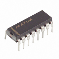
MAX807LEPE+ Maxim Integrated Products, MAX807LEPE+ Datasheet - Page 3

MAX807LEPE+
Manufacturer Part Number
MAX807LEPE+
Description
IC SUPERVISOR MPU 16-DIP
Manufacturer
Maxim Integrated Products
Type
Battery Backup Circuitr
Datasheet
1.MAX807NEWE.pdf
(16 pages)
Specifications of MAX807LEPE+
Number Of Voltages Monitored
1
Reset
Active High/Active Low
Reset Timeout
140 ms Minimum
Voltage - Threshold
4.675V
Operating Temperature
-40°C ~ 85°C
Mounting Type
Through Hole
Package / Case
16-DIP (0.300", 7.62mm)
Monitored Voltage
4.675 V
Output Type
Active High, Active Low
Manual Reset
Resettable
Watchdog
Watchdog
Battery Backup Switching
Backup
Supply Voltage (max)
5.5 V
Supply Voltage (min)
0 V
Supply Current (typ)
70 uA
Maximum Power Dissipation
842 mW
Maximum Operating Temperature
+ 85 C
Mounting Style
Through Hole
Minimum Operating Temperature
- 40 C
Power Fail Detection
Yes
Undervoltage Threshold
4.6 V
Overvoltage Threshold
4.75 V
Power-up Reset Delay (typ)
280 ms
Lead Free Status / RoHS Status
Lead free / RoHS Compliant
Output
-
Lead Free Status / Rohs Status
Lead free / RoHS Compliant
ELECTRICAL CHARACTERISTICS (continued)
(V
V
RESET, LOW LINE, AND WATCHDOG TIMER
BATT ON Output
Short-Circuit Current
Reset Threshold
Reset Threshold Hysteresis
LOW LINE to RESET
Threshold Voltage
LOW LINE Threshold,
V
V
V
RESET Active-Timeout Period
Watchdog-Timeout Period
Minimum Watchdog Input
Pulse Width
RESET Output Voltage
RESET Output
Short-Circuit Current
RESET Output Voltage
RESET Output
Short-Circuit Current
LOW LINE Output Voltage
LOW LINE Output
Short-Circuit Current
WDO Output Voltage
WDO Output
Short-Circuit Current
WDI Threshold Voltage
(Note 4)
WDI Input Current
BATT
CC
CC
CC
CC
Rising
to RESET Delay
to LOW LINE Delay
= 4.60V to 5.5V for the MAX807L, V
= 2.8V, V
PARAMETER
PFI
Full-Featured µP Supervisory Circuit with
= 0V, T
_______________________________________________________________________________________
A
= T
MIN
SYMBOL
to T
V
V
t
V
t
I
I
I
I
V
V
V
WD
RST
RP
SC
SC
SC
SC
LR
MAX
LL
IH
IH
IL
. Typical values are tested with V
CC
Sink current
Source current, V
V
V
MAX807L
MAX807N
MAX807M
V
V
V
V
I
V
I
I
Output sink current, V
Output source current
I
I
Output sink current
Output source current, V
I
I
Output sink current, V
Output source current
I
I
Output sink current
Output source current
Reset deasserted, WDI = 0V
Reset deasserted, WDI = V
SINK
SINK
SOURCE
SINK
SOURCE
SINK
SOURCE
SINK
SOURCE
CC
CC
CC
CC
CC
IL
BATT
= 4.50V to 5.5V for the MAX807N, V
= 0.8V, V
rising and falling
falling
falling at 1mV/µs
falling at 1mV/µs
rising
= 50µA,
= 3.2mA, V
= 3.2mA
= 3.2mA, V
= 3.2mA
= 0V, V
= 0.1mA
= 5mA
= 5mA
= 5mA
IH
CC
CONDITIONS
= 0.75 x V
CC
CC
CC
falling
= 4.25V
= 4.25V
= 0V, V
CC
CC
±1.5% Reset Accuracy
CC
= 4.25V
= 4.25V
CC
CC
= 4.25V
BATT
MAX807L
MAX807N
MAX807M
V
MAX807_C
V
MAX807_E/M
CC
CC
CC
= 5V and T
= 1V,
= 1.2V,
= 2.8V
A
CC
V
V
V
V
0.75 x V
= +25°C, unless otherwise noted.)
CC
CC
CC
CC
4.600
4.500
4.350
1.12
MIN
= 4.35V to 5.5V for the MAX807M,
140
100
-50
30
- 1.5
- 1.5
- 1.5
- 1.5
CC
V
CC
4.675
4.575
4.425
TYP
4.73
4.63
4.48
200
-10
1.6
0.1
1.6
70
13
52
26
24
60
60
15
28
20
35
20
16
5
- 0.1
4.750
4.650
4.500
MAX
4.81
4.71
4.56
2.24
280
0.3
0.3
0.4
0.4
0.4
0.4
0.8
70
50
UNITS
mA
mA
mA
mA
mA
mV
mV
ms
µA
µs
µs
ns
V
V
V
V
V
V
V
s
3


