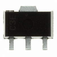
S-812C25AUA-C2FT2G Seiko Instruments, S-812C25AUA-C2FT2G Datasheet - Page 18

S-812C25AUA-C2FT2G
Manufacturer Part Number
S-812C25AUA-C2FT2G
Description
IC REG LDO 30MA 2.5V SOT-89-3
Manufacturer
Seiko Instruments
Datasheet
1.S-812C40AMC-C2UT2G.pdf
(53 pages)
Specifications of S-812C25AUA-C2FT2G
Regulator Topology
Positive Fixed
Voltage - Output
2.5V
Voltage - Input
Up to 16V
Voltage - Dropout (typical)
0.32V @ 10mA
Number Of Regulators
1
Current - Output
30mA (Min)
Operating Temperature
-40°C ~ 85°C
Mounting Type
Surface Mount
Package / Case
SC-62, SOT-89, TO-243 (3 Leads + Tab)
Number Of Outputs
1
Polarity
Positive
Input Voltage Max
18 V
Output Voltage
2.5 V
Output Type
Fixed
Dropout Voltage (max)
0.95 V
Output Current
75 mA
Line Regulation
20 mV
Load Regulation
30 mV
Voltage Regulation Accuracy
2 %
Maximum Power Dissipation
1000 mW
Maximum Operating Temperature
+ 85 C
Mounting Style
SMD/SMT
Minimum Operating Temperature
- 40 C
Lead Free Status / RoHS Status
Lead free / RoHS Compliant
Current - Limit (min)
-
Lead Free Status / Rohs Status
Lead free / RoHS Compliant
Other names
728-1017-2
18
HIGH OPERATING VOLTAGE CMOS VOLTAGE REGULATOR
S-812C Series
3. Power-off function (ON/OFF pin)
4. Short-circuit protection circuit
This function starts and stops the regulator.
When the ON/OFF pin is set to power-off level, the entire internal circuit stops operating, and the built-in
P-channel MOS FET output transistor between the VIN and VOUT pin is turned off, in order to reduce
the current consumption significantly. The VOUT pin is set to the V
resistor of several MΩ between the VOUT and VSS pin.
The ON/OFF pin is configured as shown in Figure 17 Since the ON/OFF pin is neither pulled down nor
pulled up internally, do not use it in the floating state. Note that if applying the voltage of V
more, the current flows to V
When not using the power-off pin in the product with the power-off function, connect the ON/OFF pin to
the VIN pin (in positive logic), or to the VSS pin (in negative logic).
The output voltage may increase by stopping regulation when a lower current (less than 100 μA) is
applied.
If the output voltage increased during power-off, pull the VOUT pin down to the VSS pin and set the
ON/OFF pin to the power-down level.
In the S-812C Series, users are able to select whether to set the short circuit protection, which protects
the output capacitor from short-circuiting the VOUT and VSS pin.
The short circuit protection circuit controls the output current against voltage V
Characteristics (Typical Data) 1”, and limits the output current at approx. 40 mA even if the VOUT and
VSS pins are short-circuited.
However, this short circuit protection circuit does not work as for thermal protection. Pay attention to the
conditions of input voltage and load current so that, under the usage condition including short circuit, the
loss of the IC will not exceed power dissipation of the package.
Even if pins are not short-circuited, this protection circuit works to limit the current to the specified value,
in order to protect the output capacitor, when the output current and the potential difference between
input and output voltages increase.
In the product without the short circuit protection circuit, the S-812C Series allows the relatively larger
current because this protection circuit is detached.
Logic Type
B
B
ON/OFF
“H”: Power on
“L”: Power off
ON/OFF Pin
Figure 17
VSS
VIN
IN
via a parasitic diode in the IC.
Internal Circuits
Operation
Seiko Instruments Inc.
Stop
Table 11
VOUT Pin Voltage
Set value
V
SS
level
SS
level by the internal dividing
Current Consumption
OUT
, as seen in “
I
I
SS2
SS
IN
Rev.5.0
+ 0.3 V or
_00


