MINISMDC075F-2 Tyco Electronics, MINISMDC075F-2 Datasheet - Page 8
MINISMDC075F-2
Manufacturer Part Number
MINISMDC075F-2
Description
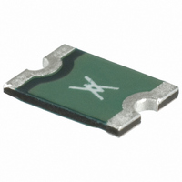
POLYSWITCH .75A RESET FUSE SMD
Manufacturer
Tyco Electronics
Series
PolySwitch®r
Type
PolySwitch Resettable Fusesr
Specifications of MINISMDC075F-2
R Min/max
0.110 ~ 0.450 Ohm
Voltage - Max
13.2V
Time To Trip
0.2s
Current - Hold (ih) (max)
750mA
Current - Trip (it)
1.5A
Current - Max
100A
Package / Case
1812 (4532 Metric)
Tripping Current
1.5A
Initial Resistance Max
0.450ohm
Operating Voltage
13.2V
Approval Bodies
CSA, TUV
Approval Category
UL Recognised
External Depth
0.62mm
External Length /
RoHS Compliant
Hold Current
0.75 Amp
Trip Current
1.5 Amps
Current Rating (max)
100 Amps
Resistance
0.45 Ohms
Maximum Voltage
13.2 Volts
Termination Style
Solder Pad
Mounting Style
SMD/SMT
Current Rating
100 Amps
Dimensions
4.73 mm L x 3.41 mm W x 0.62 mm H
Lead Free Status / RoHS Status
Lead free / RoHS Compliant
Lead Free Status / RoHS Status
Lead free / RoHS Compliant
Other names
MINISMDC075FTR
RF1404-000
RF1404-000
Available stocks
Company
Part Number
Manufacturer
Quantity
Price

Company:
Part Number:
MINISMDC075F-2
Manufacturer:
TYCO
Quantity:
11 340
Part Number:
MINISMDC075F-2
Manufacturer:
TE/泰科
Quantity:
20 000


R A D I A L - L E A D E D D E V I C E S F O R E L E C T R O N I C S A P P L I C A T I O N S
16V High Temperature
6V
The RUSBF series devices were developed for the
USB serial bus specification in computer and multi-
media applications.
Part
number
RUSBF090
RUSBF110
RUSBF135
RUSBF160
RUSBF185
RUSBF250
**
The RUSBF series devices were developed for the
USB serial bus specification in computer and multi-
media applications. These 6V products are particular-
ly well suited for USB computer monitor protection
applications where through-hole devices are still the
preferred solution.
Part
number
RUSBF075
RUSBF120
RUSBF155
**
Device may withstand higher interrupt current at lower voltages. Each application will need to be individually evaluated.
Device may withstand higher interrupt current at lower voltages. Each application will need to be individually evaluated.
0.90
1.10
1.35
1.60
1.85
2.50
0.75
1.20
1.55
(A)
(A)
I
I
H
H
1.8
2.2
2.7
3.2
3.7
5.0
1.30
2.00
2.65
(A)
(A)
ELV Compliant, RoHS Compliant
I
ELV Compliant, RoHS Compliant
I
T
T
V max.
V max.
(V)
(V)
16
16
16
16
16
16
6
6
6
I
I
max.**
max.**
(A)
(A)
40
40
40
40
40
40
40
40
40
Figure 16
Figure 17
A
A
C
R
R
C
B
1
1
B
(Ω)
(Ω)
max.
0.18
0.14
0.12
0.11
0.09
0.06
max.
0.23
0.14
0.10
Lead size
Ø 0.51 (0.020)
24 AWG
Lead size
Ø 0.51 (0.020)
24 AWG
5
Agency
recognition
UL, TÜV, CSA
UL, TÜV, CSA
UL, TÜV, CSA
UL, TÜV, CSA
UL, TÜV, CSA
UL, TÜV, CSA
Agency
recognition
UL, TÜV, CSA
UL, TÜV, CSA
UL, TÜV, CSA
10.2 (0.40)
11.4 (0.45)
A
(max.)
A
(max.)
Dimensions (millimeters/ inches )
7.4 (0.29)
7.4 (0.29)
8.9 (0.35)
8.9 (0.35)
Dimensions (millimeters/ inches )
6.9 (0.27)
6.9 (0.27)
6.9 (0.27)
12.2 (0.48)
14.2 (0.56)
13.5 (0.53)
15.2 (0.60)
15.7 (0.62)
18.3 (0.72)
11.4 (0.45)
11.7 (0.46)
11.7 (0.46)
B
(max.)
B
(max.)
5.08 (0.20)
5.08 (0.20)
5.08 (0.20)
5.08 (0.20)
5.08 (0.20)
5.08 (0.20)
5.08 (0.20)
5.08 (0.20)
5.08 (0.20)
C
(nom.)
C
(nom.)
Fig.
Fig.
17
17
17
16
16
16
16
16
16
Related parts for MINISMDC075F-2
Image
Part Number
Description
Manufacturer
Datasheet
Request
R

Part Number:
Description:
Battery Interconnection System for Portable Electronics; BU CONN FS6 8POS DIP TYPE ASSY ( AMP )
Manufacturer:
Tyco Electronics
Part Number:
Description:
Manufacturer:
Tyco Electronics
Datasheet:
Part Number:
Description:
Manufacturer:
Tyco Electronics
Datasheet:


