250R180F Littelfuse Inc, 250R180F Datasheet
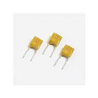
PTC RESETBL 60V/250V .180A RAD

250R180F

Manufacturer Part Number
250R180F
Description
PTC RESETBL 60V/250V .180A RAD
Manufacturer
Littelfuse Inc
Series
POLYFUSE® 250Rr
Datasheet

Specifications of 250R180F

R Min/max
0.800 ~ 4.000 Ohm
Voltage - Max
250V
Time To Trip
21s
Current - Hold (ih) (max)
180mA
Current - Trip (it)
650mA
Current - Max
10A
Package / Case
Radial
Hold Current
0.18 Amp
Trip Current
0.65 Amp
Current Rating (max)
10 Amps
Resistance
4 Ohms
Maximum Voltage
60 VoltsDC
Termination Style
Radial
Mounting Style
Through Hole
Current Rating
10 Amps
Operating Temperature Range
- 40 C to + 85 C
Holding Current
180mA
Tripping Current
650mA
Initial Resistance Max
4ohm
Operating Voltage
60VDC
Ptc Fuse Case
Radial Leaded
Fuse Terminals
Radial Leaded
Rohs Compliant
Yes
Lead Free Status / RoHS Status
Lead free / RoHS Compliant
Lead Free Status / RoHS Status
Lead free / RoHS Compliant, Lead free / RoHS Compliant
© 2010 Littelfuse, Inc
Specifications are subject to change without notice.
Please refer to www.littelfuse.com/series/250R.html for current information.
Items with T at end of part number = pre-tripped device. See Part Ordering Number System section of this data sheet for additional information.
I
I
V
V
I
P
* Effective January 1, 2010, all 250R PTC products will be manufactured Halogen Free (HF). Existing Non-Halogen Free 250R PTC products may continue to be sold, until supplies are depleted.
hold
trip
op
max
int
d
Agency Approvals
AGENCY
Electrical Characteristics
Part Number
= The device regular operation voltage
= Power dissipated from device when in the tripped state at 23°C still air.
= Maximum voltage the device can withstand without damage at rated current (I max)
= Trip current: minimum current at which the device will trip in 23°C still air.
= Hold current: maximum current device will pass without tripping in 23°C still air.
= Maximum fault current device can withstand without damage at rated voltage (V
250R120-RA
250R120-RC
250R145-RA
250R145-RB
250R120-RF
250R120-R1
250R120-R2
250R120-R3
250R080T
250R120T
250R145T
250R180T
250R080
250R120
250R145
250R180
AGENCY FILE NUMBER
E183209
R50120008
250R Series
0.145
0.145
0.145
0.145
0.08
0.08
0.12
0.12
0.12
0.12
0.12
0.12
0.12
0.12
0.18
0.18
I
(A)
hold
0.24
0.24
0.24
0.24
0.24
0.24
0.24
0.24
0.29
0.29
0.29
0.29
0.65
0.65
0.16
0.16
I
(A)
trip
V
250/60
250/60
250/60
250/60
250/60
250/60
250/60
250/60
250/60
250/60
250/60
250/60
250/60
250/60
250/60
250/60
Radial Leaded > 250R Series
POLYFUSE
int
V
max
/ V
op
I
(A)
10
10
max
3
3
3
3
3
3
3
3
3
3
3
3
3
3
Revised: July 12, 2010
max
)
typ.
(W)
®
P
1.8
1.8
1
1
1
1
1
1
1
1
1
1
1
1
1
1
99
d
Resettable PTCs
R
R
R
Caution: Operation beyond the specified rating may result in damage and possible arcing
and flame.
min
typ
1max
Description
The 250R Series is designed to protect against short
duration high voltage fault currents (power cross or power
induction surge) typically found in telecom applications
(250Vrms). The series can be used to help telecom
networking equipment meet the protection requirements
specified in ITU K.20 and K.21.
Features
Applications
Current
Maximum Time
= Typical resistance of device in initial (un-soldered) state.
range, 60VDC operating
voltage
Equipment (CPE)
telecom centers
0.35
0.35
= Minimum resistance of device in initial (un-soldered) state.
(A)
= Maximum resistance of device at 20°C measured one hour after tripping.
1
1
1
1
1
1
1
1
1
1
1
1
1
1
To Trip
(Sec.)
Time
0.85
0.7
0.8
0.7
2.5
2.5
2.0
1.5
1.0
1.2
21
20
3
3
1
5
R
(Ω)
5.4
4.5
5.4
0.8
1.4
14
15
4
7
6
6
8
8
7
3
3
min
Resistance
R
10.5
10.5
(Ω)
5.5
2.2
3.9
7 .5
7 .5
22
22
10
12
8
9
9
6
6
typ
resistance ranges available
Free and Halogen-Free*
R
(Ω)
4.5
33
33
16
16
14
16
16
16
16
16
14
12
14
14
1max
4
Approvals
X
X
X
X
X
X
X
X
X
X
X
X
X
X
X
X
Agency
250R Series
X
X
X
X
X
X
X
X
X
X
X
X
X
X
X
X

Related parts for 250R180F

250R180F Summary of contents

Page 1

Series Agency Approvals AGENCY AGENCY FILE NUMBER E183209 R50120008 Electrical Characteristics I I hold trip Part Number (A) (A) 250R080 0.08 0.16 250R080T 0.08 0.16 250R120 0.12 0.24 250R120-RA 0.12 0.24 250R120-RC 0.12 0.24 250R120-RF 0.12 0.24 250R120-R1 0.12 ...

Page 2

POLYFUSE Temperature Rerating -40°C -20°C Part Number 250R080 0.12 0.11 250R080T 0.12 0.11 250R120 0.18 0.16 250R120T 0.18 0.16 250R145 0.26 0.20 250R145T 0.26 0.20 250R180 0.28 0.23 250R180T 0.28 0.23 Average Time Current Curves 100000 10000 1000 100 10 ...

Page 3

Agency Specification Selection Guide For Telecom and Networking Applications Product Lightning 250R120 ITU K.20/21/45 – 1.5kV 10/700μs 250R145 ITU K.20/21/45 – 4kV 10/700μs* ITU K.20/21/45 – 1.5kV 10/700μs 250R180 ITU K.20/21/45 – 4kV 10/700μs* Telcordia GR – 974 – 1.0kV ...

Page 4

POLYFUSE Soldering Parameters - Wave Soldering Condition Wave Soldering Peak Temp/ Duration Time 260°C > 220°C 2 Sec ~ 20 Sec Preheat 140°C ~ 180°C 180 Sec ~ 210 Sec Storage Condition 0°C~35°C N environment for lead-free. 2 side of ...

Page 5

Dimensions Figure 1 A Inches mm Part Number Figure Max. Max. 250R080 1 0.23 5.8 250R080T 1 0.23 5.8 250R120 2 0.26 6.5 250R120-RA 2 0.26 6.5 250R120-RC 2 0.26 6.5 ...

Page 6

... Series ® Resettable PTCs Radial Leaded > 250R Series BLANK: Bulk R: Tape & Ammo I Packaging hold ...

Page 7

Tape and Ammo Specifications Devices taped using EIA468-B/IE286-2 standards. See table below and Figure 1 for details. Dimension Carrier tape width Hold down tape width Top distance between tape edges Sprocket hole position Sprocket hole diameter* Abscissa to plane (straight ...

Related keywords