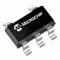
TC1015-2.85VCT713 Microchip Technology, TC1015-2.85VCT713 Datasheet - Page 12

TC1015-2.85VCT713
Manufacturer Part Number
TC1015-2.85VCT713
Description
IC REG LDO 2.85V 100MA SOT23A-5
Manufacturer
Microchip Technology
Datasheet
1.TC1014-3.3VCT713.pdf
(22 pages)
Specifications of TC1015-2.85VCT713
Regulator Topology
Positive Fixed
Voltage - Output
2.85V
Voltage - Input
Up to 6V
Voltage - Dropout (typical)
0.18V @ 100mA
Number Of Regulators
1
Current - Output
100mA (Min)
Operating Temperature
-40°C ~ 125°C
Mounting Type
Surface Mount
Package / Case
SOT-23-5, SC-74A, SOT-25
Lead Free Status / RoHS Status
Lead free / RoHS Compliant
Current - Limit (min)
-
Other names
Q1143705
Available stocks
Company
Part Number
Manufacturer
Quantity
Price
Part Number:
TC1015-2.85VCT713
Manufacturer:
MICROCHIP/微芯
Quantity:
20 000
TC1014/TC1015/TC1185
4.0
The TC1014, TC1015 and TC1185 are precision fixed
output voltage regulators (if an adjustable version is
needed, see the TC1070, TC1071 and TC1187 data
sheet (DS21353). Unlike bipolar regulators, the
TC1014, TC1015 and TC1185 supply current does not
increase with load current. In addition, the LDOs’ out-
put voltage is stable using 1 µF of capacitance over the
entire specified input voltage range and output current
range.
Figure 4-1
regulator is enabled anytime the shutdown input
(SHDN) is at or above V
at or below V
logic gate or I/O port of a microcontroller. If the SHDN
input is not required, it should be connected directly to
the input supply. While in shutdown, the supply current
decreases to 0.05 µA (typical) and V
volts.
FIGURE 4-1:
DS21335E-page 12
(to CMOS Logic or Tie
+
Battery
Shutdown Control
to V
DETAILED DESCRIPTION
IN
+
1 µF
shows a typical application circuit. The
if unused)
IL
. SHDN may be controlled by a CMOS
V
GND
SHDN
IN
TC1014
TC1015
TC1185
Typical Application Circuit.
IH
, and disabled when SHDN is
Bypass
V
OUT
OUT
470 pF
Reference
Bypass Cap
(Optional)
+
1 µF
falls to zero
V
OUT
4.1
A 470 pF capacitor connected from the Bypass input to
ground reduces noise present on the internal
reference, which in turn, significantly reduces output
noise. If output noise is not a concern, this input may be
left unconnected. Larger capacitor values may be
used, but results in a longer time period to rated output
voltage when power is initially applied.
4.2
A 1 µF (min) capacitor from V
The output capacitor should have an effective series
resistance greater than 0.1Ω and less than 5Ω. A 1 µF
capacitor should be connected from V
is more than 10 inches of wire between the regulator
and the AC filter capacitor, or if a battery is used as the
power source. Aluminum electrolytic or tantalum
capacitor types can be used. (Since many aluminum
electrolytic capacitors freeze at approximately -30°C,
solid tantalums are recommended for applications
operating below -25°C.) When operating from sources
other than batteries, supply-noise rejection and
transient response can be improved by increasing the
value of the input and output capacitors and employing
passive filtering techniques.
4.3
A 1 µF capacitor should be connected from V
if there is more than 10 inches of wire between the
regulator and this AC filter capacitor, or if a battery is
used as the power source. Aluminum electrolytic or
tantalum capacitors can be used (since many
aluminum
approximately -30°C, solid tantalum is recommended
for applications operating below -25°C). When
operating from sources other than batteries, supply-
noise rejection and transient response can be
improved by increasing the value of the input and
output capacitors and employing passive filtering
techniques.
Bypass Input
Output Capacitor
Input Capacitor
electrolytic
© 2007 Microchip Technology Inc.
capacitors
OUT
to ground is required.
IN
to GND if there
freeze
IN
to GND
at


