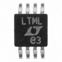
LT1962EMS8-3#TR Linear Technology, LT1962EMS8-3#TR Datasheet - Page 15

LT1962EMS8-3#TR
Manufacturer Part Number
LT1962EMS8-3#TR
Description
IC LDO REG LOWNOISE 3V 8-MSOP
Manufacturer
Linear Technology
Datasheet
1.LT1962EMS8PBF.pdf
(16 pages)
Specifications of LT1962EMS8-3#TR
Regulator Topology
Positive Fixed
Voltage - Output
3V
Voltage - Input
Up to 20V
Voltage - Dropout (typical)
0.27V @ 300mA
Number Of Regulators
1
Current - Output
300mA
Current - Limit (min)
320mA
Operating Temperature
-40°C ~ 125°C
Mounting Type
Surface Mount
Package / Case
8-MSOP, Micro8™, 8-uMAX, 8-uSOP,
Lead Free Status / RoHS Status
Contains lead / RoHS non-compliant
Other names
LT1962EMS8-3TR
Available stocks
Company
Part Number
Manufacturer
Quantity
Price
APPLICATIO S I FOR ATIO
from the 1.22V reference when the output is forced to 20V.
The top resistor of the resistor divider must be chosen to
limit the current into the ADJ pin to less than 5mA when the
ADJ pin is at 7V. The 13V difference between OUT and ADJ
pin divided by the 5mA maximum current into the ADJ pin
yields a minimum top resistor value of 2.6k.
In circuits where a backup battery is required, several
different input/output conditions can occur. The output
voltage may be held up while the input is either pulled to
ground, pulled to some intermediate voltage or is left open
circuit. Current flow back into the output will follow the
curve shown in Figure 7.
When the IN pin of the LT1962 is forced below the OUT pin
or the OUT pin is pulled above the IN pin, input current will
typically drop to less than 2 A. This can happen if the input
of the device is connected to a discharged (low voltage)
battery and the output is held up by either a backup battery
PACKAGE DESCRIPTIO
U
(0.18)
** DIMENSION DOES NOT INCLUDE INTERLEAD FLASH OR PROTRUSIONS.
0.007
* DIMENSION DOES NOT INCLUDE MOLD FLASH, PROTRUSIONS OR GATE BURRS. MOLD FLASH,
PROTRUSIONS OR GATE BURRS SHALL NOT EXCEED 0.006" (0.152mm) PER SIDE
INTERLEAD FLASH OR PROTRUSIONS SHALL NOT EXCEED 0.006" (0.152mm) PER SIDE
U
Information furnished by Linear Technology Corporation is believed to be accurate and reliable.
However, no responsibility is assumed for its use. Linear Technology Corporation makes no represen-
tation that the interconnection of its circuits as described herein will not infringe on existing patent rights.
(0.53 0.015)
0.021 0.006
W
U
Dimensions in inches (millimeters) unless otherwise noted.
0 – 6 TYP
U
(LTC DWG # 05-08-1660)
8-Lead Plastic MSOP
MS8 Package
SEATING
PLANE
or a second regulator circuit. The state of the SHDN pin will
have no effect on the reverse output current when the
output is pulled above the input.
(3.00 0.102)
0.193 0.006
0.118 0.004*
(4.90 0.15)
0.009 – 0.015
(0.22 – 0.38)
(1.10)
0.043
MAX
100
90
80
70
60
50
40
30
20
10
0.0256
0
(0.65)
BSC
0
1
T
V
CURRENT FLOWS
INTO OUTPUT PIN
V
Figure 7. Reverse Output Current
8
J
IN
OUT
LT1962-3.3
= 25 C
1
2 3
= 0V
7 6 5
= V
2
LT1962-3
ADJ
LT1962-1.8
LT1962-2.5
OUTPUT VOLTAGE (V)
4
3
(LT1962)
LT1962-1.5
4
(3.00 0.102)
0.118 0.004**
(0.86)
0.034
REF
0.005 0.002
(0.13 0.05)
5
MSOP (MS8) 1100
6
LT1962-5
LT1962 Series
LT1962
7
8
9
1962 F07
10
15


