LT1585ACT Linear Technology, LT1585ACT Datasheet - Page 6
LT1585ACT
Manufacturer Part Number
LT1585ACT
Description
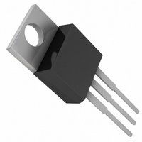
IC LDO REG 5A ADJ TO220-3
Manufacturer
Linear Technology
Datasheet
1.LT1585ACT-3.3PBF.pdf
(12 pages)
Specifications of LT1585ACT
Regulator Topology
Positive Adjustable
Voltage - Output
1.25 ~ 5.5 V
Voltage - Input
2.45 ~ 7 V
Voltage - Dropout (typical)
1.2V @ 5A
Number Of Regulators
1
Current - Limit (min)
5A
Operating Temperature
0°C ~ 125°C
Mounting Type
Through Hole
Package / Case
TO-220-3 (Straight Leads)
Lead Free Status / RoHS Status
Contains lead / RoHS non-compliant
Current - Output
-
Available stocks
Company
Part Number
Manufacturer
Quantity
Price
Company:

Part Number:
LT1585ACT
Manufacturer:
LT
Quantity:
1 895
Part Number:
LT1585ACT#PBF
Manufacturer:
LINEAR/凌特
Quantity:
20 000
Part Number:
LT1585ACT-1.5
Manufacturer:
LT/凌特
Quantity:
20 000
Company:
Part Number:
LT1585ACT-15
Manufacturer:
LT
Quantity:
5 510
Company:
Part Number:
LT1585ACT-3.3
Manufacturer:
LT
Quantity:
5 510
Part Number:
LT1585ACT-3.3
Manufacturer:
LT/凌特
Quantity:
20 000
Part Number:
LT1585ACT-3.3#PBF
Manufacturer:
LINEAR/凌特
Quantity:
20 000
Company:
Part Number:
LT1585ACT-5.0
Manufacturer:
TECHODE
Quantity:
69 800


LT1585A/LT1585A-3.3
APPLICATIONS
tor tolerance (sometimes ranging up to ±100%), equiva-
lent series resistance, equivalent series inductance and
capacitance temperature coefficient. The LT1585A/
LT1585A-3.3 frequency compensation optimizes fre-
quency response with low ESR capacitors. In general, use
capacitors with an ESR of less than 1Ω.
On the adjustable LT1585A, bypassing the adjust terminal
improves ripple rejection and transient response. Bypass-
ing the adjust pin increases the required output capacitor
value. The value of 100µF tantalum or aluminum covers all
cases of bypassing the adjust terminal. With no adjust pin
bypassing, smaller values of capacitors provide equally
good results.
Normally, capacitor values on the order of several hun-
dred microfarads are used on the output of the regulators
to ensure good transient response with heavy load current
changes. Output capacitance can increase without limit
and larger values of output capacitance further improve
the stability and transient response of the LT1585A/
LT1585A-3.3.
Large load current changes are exactly the situation
presented by modern microprocessors. The load current
step contains higher order frequency components that
the output decoupling network must handle until the
regulator throttles to the load current level. Capacitors are
not ideal elements and contain parasitic resistance and
inductance. These parasitic elements dominate the change
in output voltage at the beginning of a transient load step
change. The ESR of the output capacitors produces an
instantaneous step in output voltage (∆V = ∆I • ESR). The
ESL of the output capacitors produces a droop propor-
tional to the rate of change of output current (V = L •
∆I/∆t). The output capacitance produces a change in
output voltage proportional to the time until the regulator
can respond (∆V = ∆t • ∆I/C). These transient effects are
illustrated in Figure 1.
The use of capacitors with low ESR, low ESL and good
high frequency characteristics is critical in meeting the
output voltage tolerances of these high speed micropro-
6
U
INFORMATION
U
W
U
cessors. These requirements dictate a combination of
high quality, surface mount tantalum capacitors and
ceramic capacitors. The location of the decoupling net-
work is critical to transient response performance. Place
the decoupling network as close as possible to the pro-
cessor pins because trace runs from the decoupling
capacitors to the processor pins are inductive. The ideal
location for the decoupling network is actually inside the
microprocessor socket cavity. In addition, use large power
and ground plane areas to minimize distribution drops.
A possible stability problem that occurs in monolithic
linear regulators is current limit oscillations. The LT1585A/
LT1585A-3.3 essentially have a flat current limit over the
range of input supply voltage. The lower current limit
rating and 7V maximum supply voltage rating for these
devices permit this characteristic. Current limit oscilla-
tions are typically nonexistent, unless the input and out-
put decoupling capacitors for the regulators are mounted
several inches from the terminals.
Protection Diodes
In normal operation, the LT1585A/LT1585A-3.3 do not
require any protection diodes. Older 3-terminal regulators
require protection diodes between the output pin and the
input pin or between the adjust pin and the output pin to
prevent die overstress.
On the adjustable LT1585A, internal resistors limit inter-
nal current paths on the adjust pin. Therefore, even with
bypass capacitors on the adjust pin, no protection diode
is needed to ensure device safety under short-circuit
conditions.
ESR
EFFECTS
ESL
EFFECTS
SLOPE,
V
t
=
∆I
C
Figure 1
POINT AT WHICH REGULATOR
TAKES CONTROL
CAPACITANCE
EFFECTS
LT1585A • F01
1585afa
Related parts for LT1585ACT
Image
Part Number
Description
Manufacturer
Datasheet
Request
R

Part Number:
Description:
7A/ 4.6A/ 3A Low Dropout Fast Response Positive Regulators Adjustable and Fixed
Manufacturer:
Linear Technology
Datasheet:
Part Number:
Description:
Fixed 1.5V/ 4.6A and 5A Low Dropout/ Fast Response GTL+ Regulators
Manufacturer:
Linear Technology
Part Number:
Description:
CD ROM LINEARVIEW DATASHEETS
Manufacturer:
Linear Technology

Part Number:
Description:
Standalone Linear Li-Ion Battery Charger with Thermal Regulation in ThinSOT
Manufacturer:
Linear Technology Corporation
Datasheet:
Part Number:
Description:
Low noise, high frequency, 8th order linear phase lowpass filter
Manufacturer:
Linear Technology Corporation
Datasheet:
Part Number:
Description:
Manufacturer:
Linear Technology Corporation
Datasheet:
Part Number:
Description:
Manufacturer:
Linear Technology Corporation
Datasheet:
Part Number:
Description:
Manufacturer:
Linear Technology Corporation
Datasheet:
Part Number:
Description:
Manufacturer:
Linear Technology Corporation
Datasheet:
Part Number:
Description:
Manufacturer:
Linear Technology Corporation
Datasheet:
Part Number:
Description:
Manufacturer:
Linear Technology Corporation
Datasheet:
Part Number:
Description:
Manufacturer:
Linear Technology Corporation
Datasheet:
Part Number:
Description:
Dual and Quad, JFET Input Precision High Speed Op Amps
Manufacturer:
Linear Technology Corporation
Datasheet:
Part Number:
Description:
Manufacturer:
Linear Technology Corporation
Datasheet:
Part Number:
Description:
1, 2, 6 and 8 Channel, 10-Bit Serial I/O Data Acquisition Systems
Manufacturer:
Linear Technology Corporation
Datasheet: