BA033CC0WFP-E2 Rohm Semiconductor, BA033CC0WFP-E2 Datasheet - Page 8
BA033CC0WFP-E2
Manufacturer Part Number
BA033CC0WFP-E2
Description
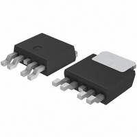
IC REG LDO 1A 3.3V SHTDN TO252-5
Manufacturer
Rohm Semiconductor
Specifications of BA033CC0WFP-E2
Regulator Topology
Positive Fixed
Voltage - Output
3.3V
Voltage - Input
Up to 25V
Voltage - Dropout (typical)
0.3V @ 500mA
Number Of Regulators
1
Current - Output
1A (Max)
Operating Temperature
-40°C ~ 125°C
Mounting Type
Surface Mount
Package / Case
TO-252-4, DPak (4 Leads + Tab), TO-252AD
Number Of Outputs
1
Polarity
Positive
Output Voltage
3.3 V
Output Type
Fixed
Dropout Voltage (max)
0.5 V at 500 mA
Output Current
1 A
Line Regulation
100 mV
Load Regulation
150 mV
Voltage Regulation Accuracy
2 %
Maximum Power Dissipation
1.3 W
Maximum Operating Temperature
+ 125 C
Mounting Style
SMD/SMT
Minimum Operating Temperature
- 40 C
Lead Free Status / RoHS Status
Lead free / RoHS Compliant
Current - Limit (min)
-
Lead Free Status / Rohs Status
Lead free / RoHS Compliant
Available stocks
Company
Part Number
Manufacturer
Quantity
Price

Company:
Part Number:
BA033CC0WFP-E2
Manufacturer:
ROHM
Quantity:
973
Part Number:
BA033CC0WFP-E2
Manufacturer:
ROHM/罗姆
Quantity:
20 000


●Peripheral Circuit Considerations
●Vo Terminal
BA□□DD0T
BA□□DD0WT
© 2011 ROHM Co., Ltd. All rights reserved.
www.rohm.com
IC
・Vcc Terminal
・GND Terminal
・CTL Terminal
Please attach an anti-oscillation capacitor between V
due to factors such as temperature changes, making it impossible to completely stop oscillations. Please use a tantalum
capacitor or aluminum electrolysis capacitor with favorable characteristics and small internal series resistance (ESR) even at
low temperatures. The output fluctuates regardless of whether the ESR is large or small. Please use the IC within the stable
operating region while referring to the ESR characteristics reference data shown in Figs.32 through 34. In applications where
there are sudden load fluctuations, the use of a capacitor with large capacitance is recommended.
Fig.32 Output Equivalent Circuit
Please attach a capacitor (greater than 0.33µF) between the Vcc and GND.
The capacitance values will differ depending on the application, so please take this into account when configuring the terminal.
Please be sure to keep the set ground and IC ground at the same potential level so that a potential difference does not
arise between them.
If a potential difference arises between the set ground and the IC ground, the preset voltage will not be outputted, causing
the system to become unstable. Therefore, please reduce the impedance by making the ground patterns as wide as
possible and by reducing the distance between the set ground and the IC ground as much as possible.
The CTL terminal is turned ON at 2.0V and higher and OFF at 0.8V and lower within the operating power supply voltage range.
The power supply and the CTL terminal may be started up and shut down in any order without problems.
Series
Series
,BA□□CC0T
,BA□□DD0HFP
OUT
22μF
Series
,BA□□CC0FP
Series
100
10
0.1
1
0
,BA□□CC0WT
Fig.33 ESR-Io Characteristics
200
OUTPUT CURRENT:lo(mA)
(BA□□CC0)
Stable operating region
Unstable operating region
400
Unstable operating region
Series
cc
600
and GND. The capacitance of the capacitor may significantly change
Series
8/11
800
,BA□□CC0WFP
1000
10
0.1
100
1
1
1
Series
Fig.34 ESR vs Io Characteristics
10
Unstable operating region
OUTPUT CURRENT:lo(mA)
Stable operating region
(B A□□DD0)
100
Technical Note
Unstable operating region
2011.03 - Rev.C
1000
10000
Related parts for BA033CC0WFP-E2
Image
Part Number
Description
Manufacturer
Datasheet
Request
R

Part Number:
Description:
Manufacturer:
Rohm Semiconductor
Datasheet:
Part Number:
Description:
Manufacturer:
Rohm Semiconductor
Datasheet:
Part Number:
Description:
Manufacturer:
Rohm Semiconductor
Datasheet:
Part Number:
Description:
Manufacturer:
Rohm Semiconductor
Datasheet:
Part Number:
Description:
Manufacturer:
Rohm Semiconductor
Datasheet:
Part Number:
Description:
Manufacturer:
Rohm Semiconductor
Datasheet:
Part Number:
Description:
Manufacturer:
Rohm Semiconductor
Datasheet:
Part Number:
Description:
Manufacturer:
Rohm Semiconductor
Datasheet:
Part Number:
Description:
Manufacturer:
Rohm Semiconductor
Datasheet:
Part Number:
Description:
Manufacturer:
Rohm Semiconductor
Datasheet:
Part Number:
Description:
Manufacturer:
Rohm Semiconductor
Datasheet:
Part Number:
Description:
Manufacturer:
Rohm Semiconductor
Datasheet:

Part Number:
Description:
DIODE SWITCH 80V 25MA SMD5 TR
Manufacturer:
Rohm Semiconductor
Datasheet: