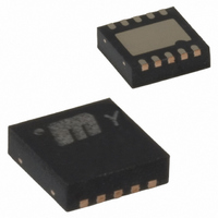
MIC2211-WOBML TR Micrel Inc, MIC2211-WOBML TR Datasheet - Page 4

MIC2211-WOBML TR
Manufacturer Part Number
MIC2211-WOBML TR
Description
IC REG LDO DUAL 3X3 10-MLF
Manufacturer
Micrel Inc
Datasheet
1.MIC2211-AAYML_TR.pdf
(10 pages)
Specifications of MIC2211-WOBML TR
Regulator Topology
Positive Fixed
Voltage - Output
1.6V, 2.9V
Voltage - Input
2.25 ~ 5.5 V
Voltage - Dropout (typical)
0.12V @ 150mA, 0.24V @ 300mA
Number Of Regulators
2
Current - Output
150mA, 300mA
Current - Limit (min)
150mA, 300mA
Operating Temperature
-40°C ~ 125°C
Mounting Type
Surface Mount
Package / Case
10-MLF®, QFN
Lead Free Status / RoHS Status
Contains lead / RoHS non-compliant
Other names
MIC2211-WOBMLTR
MIC2211-WOBMLTR
MIC2211-WOBMLTR
Absolute Maximum Rating
Supply Input Voltage (V
Enable Input Voltage (V
Power Dissipation (P
Junction Temperature ............................... –40°C to +125°C
Storage Temperature (T
Lead Temperature (soldering, 5 sec.) ........................ 260°C
Electrical Characteristics
V
–40°C ≤ T
Parameter
Output Voltage Accuracy
Output Voltage Temp.
Coefficient
Line Regulation
Load Regulation
Dropout Voltage
Ground Pin Current
Ground Pin Current in Shutdown
Ripple Rejection
Current Limit
Output Voltage Noise
Enable Input
Enable Input Voltage
Enable Input Current
Notes:
1. Exceeding the absoulte maximum ratings may damage the device.
2. The device is not guaranteed to work outside its operating ratings.
3. The maximum allowable power dissipation of any T
4. Specification for packaged product only.
5. Minimum input for line regulation test is set to V
6. Dropout voltage is defined as the input-to-output differential at which the output voltage drops 2% below its nominal value measured at 1V differen-
M9999-101905
IN
power dissipation will result in excessive die temperature, and the regulator will go into thermal shutdown.
tial. For outputs below 2.25V, dropout voltage is the input-to-output voltage differential with the minimum input voltage 2.25V. Minimum input operat-
ing voltage is 2.25V.
= V
OUT
J
≤ +125°C, unless noted.
+1.0V for higher output of the regulator pair; C
(5)
(6)
D
) ..........................Internally Limited
IN
EN
S
) .......................... –65°C to 150°C
) ......................................0V to 7V
) ....................................0V to 7V
Conditions
Variation from nominal V
V
I
I
I
I
I
I
V
f = 1kHz; C
f = 20kHz; C
V
V
C
Logic Low (Regulator Shutdown)
Logic High (Regulator Enabled)
V
V
OUT
OUT
OUT
OUT
OUT1
OUT1
IN
EN
OUT
OUT
IL
IH
OUT
(4)
< 0.6V (Regulator Shutdown)
> 1.8V (Regulator Enabled)
= V
≤ 0.4V
(1)
= 100µA to 150mA (Regulator 1 and 2)
= 100µA to 300mA (Regulator 2)
= 150mA (Regulator 1 and 2)
= 300mA (Regulator 2)
= 150mA & I
= 0V (Regulator 1)
= 0V (Regulator 2)
=1µF, C
= I
OUT
OUT2
OUT
OUT
+1V to 5.5V
OUT
A
+ 1V relative to the highest output voltage.
BYP
= 0µA
(ambient temperature) is (P
= 1.0µF ceramic; C
= 1.0µF ceramic; C
OUT2
=0.01µF, 10Hz to 100kHz
OUT
= 300mA
OUT
= 1.0µF, I
(3)
4
Operating Ratings
Supply Input Voltage (V
Enable Input Voltage (V
Junction Temperature (T
Package Thermal Resistance
BYP
OUT
BYP
MLF™-10 (θ
D(max)
= 10nF
= 100µA; T
= 10nF
= T
J(max)
JA
J
= 25°C, bold values indicate
) .................................................... 60°C/W
– T
A
) / θ
IN
EN
JA
J
) ........................ –40°C to +125°C
(2)
) ..............................2.25V to 5.5V
. Exceeding the maximum allowable
) ................................... 0V to Vin
–1.0
–2.0
–0.3
–0.6
Min
150
300
1.8
–1
–1
0.02
0.01
0.01
Typ
120
240
280
450
0.2
40
48
60
60
40
30
October 2005
Max
+1.0
+2.0
190
250
340
420
460
700
0.3
0.6
1.0
1.5
2.0
0.6
65
80
+1
+1
ppm/C
µVrms
Units
%/V
mV
mV
mV
mA
mA
µA
µA
µA
dB
dB
µA
µA
%
%
%
%
µA
V
V


