NCP1117LPST33T3G ON Semiconductor, NCP1117LPST33T3G Datasheet - Page 2
NCP1117LPST33T3G
Manufacturer Part Number
NCP1117LPST33T3G
Description
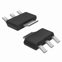
IC REG LDO 1A 3.3V SOT-223-4
Manufacturer
ON Semiconductor
Datasheet
1.NCP1117LPST50T3G.pdf
(14 pages)
Specifications of NCP1117LPST33T3G
Regulator Topology
Positive Fixed
Voltage - Output
3.3V
Voltage - Input
Up to 18V
Voltage - Dropout (typical)
1.3V @ 1A
Number Of Regulators
1
Current - Output
1A
Current - Limit (min)
1.1A
Operating Temperature
0°C ~ 125°C
Mounting Type
Surface Mount
Package / Case
SOT-223 (3 leads + Tab), SC-73, TO-261
Lead Free Status / RoHS Status
Lead free / RoHS Compliant
Available stocks
Company
Part Number
Manufacturer
Quantity
Price
Company:

Part Number:
NCP1117LPST33T3G
Manufacturer:
ON
Quantity:
24 000
Part Number:
NCP1117LPST33T3G
Manufacturer:
ON/安森美
Quantity:
20 000


Stresses exceeding Maximum Ratings may damage the device. Maximum Ratings are stress ratings only. Functional operation above the
Recommended Operating Conditions is not implied. Extended exposure to stresses above the Recommended Operating Conditions may affect
device reliability.
NOTE:
1. The maximum package power dissipation is:
2. R
Table 2. MAXIMUM RATINGS
Table 1. PIN FUNCTION DESCRIPTION
DC Input Voltage
Operating Junction Temperature Range
Operating Ambient Temperature Range
Maximum Junction Temperature Range
Power Dissipation and Thermal Characteristics
Electrostatic Discharge
Storage Temperature Range
NOTE: This device series contains ESD protection and exceeds the following tests:
Pin No.
− Power Dissipation (Note 1)
− Thermal Resistance, Junction−to−Ambient (Note 2)
− Thermal Resistance, Junction−to−Case
ESD HBM tested per AEC−Q100−002 (EIA/JESD22−A114)
ESD MM tested per AEC−Q100−003 (EIA/JESD22−A115)
Latch–up Current Maximum Rating: ≤ 150mA per JEDEC standard: JESD78
qJA
1
2
3
on a 100 x 100 mm PCB Cu thickness 1 oz; T
All voltages are referenced to GND pin.
P
D
+
Pin Name
Adj (GND)
T
J(max)
Vout
Vin
R
qJA
* T
A
A resistor divider from this pin to the Vout pin and ground sets the output voltage (Ground only for
Fixed−Mode).
The output of the regulator. A minimum of 10 mF capacitor (20 mW ≤ ESR ≤ 20 W) must be connec-
ted from this pin to ground to insure stability.
The input pin of regulator. Typically a large storage capacitor (20 mW ≤ ESR ≤ 20 W) is connected
from this pin to ground to insure that the input voltage does not sag below the minimum dropout
voltage during the load transient response. This pin must always be 1.3 V (typ.) higher than Vout in
order for the device to regulate properly.
Rating
Human Body Model
A
Machine Model
Figure 3. Block Diagram
= 25°C
http://onsemi.com
2
Description
Symbol
T
T
R
R
ESD
J(max)
T
V
P
T
STG
qJA
qJC
OP
in
A
D
Internally Limited
−55 to 150
−65 to 150
−0.3 to 18
0 to 125
0 to 125
Value
2000
108
200
15
°C/W
°C/W
Unit
°C
°C
°C
°C
W
V
V
Related parts for NCP1117LPST33T3G
Image
Part Number
Description
Manufacturer
Datasheet
Request
R

Part Number:
Description:
1.0 A Low-dropout Positive Fixed And Adjustable Voltage Regulators
Manufacturer:
ON Semiconductor
Datasheet:

Part Number:
Description:
1.0 A Low−Dropout Positive Fixed and Adjustable Voltage Regulators
Manufacturer:
ONSEMI [ON Semiconductor]
Datasheet:
Part Number:
Description:
ON Semiconductor [VOLTAGE REGULATOR]
Manufacturer:
ON Semiconductor
Datasheet:
Part Number:
Description:
357-036-542-201 CARDEDGE 36POS DL .156 BLK LOPRO
Manufacturer:
ON Semiconductor
Datasheet:
Part Number:
Description:
357-036-542-201 CARDEDGE 36POS DL .156 BLK LOPRO
Manufacturer:
ON Semiconductor
Datasheet:
Part Number:
Description:
357-036-542-201 CARDEDGE 36POS DL .156 BLK LOPRO
Manufacturer:
ON Semiconductor
Datasheet:
Part Number:
Description:
357-036-542-201 CARDEDGE 36POS DL .156 BLK LOPRO
Manufacturer:
ON Semiconductor
Datasheet:
Part Number:
Description:
357-036-542-201 CARDEDGE 36POS DL .156 BLK LOPRO
Manufacturer:
ON Semiconductor
Datasheet:
Part Number:
Description:
357-036-542-201 CARDEDGE 36POS DL .156 BLK LOPRO
Manufacturer:
ON Semiconductor
Datasheet:
Part Number:
Description:
357-036-542-201 CARDEDGE 36POS DL .156 BLK LOPRO
Manufacturer:
ON Semiconductor
Datasheet:
Part Number:
Description:
357-036-542-201 CARDEDGE 36POS DL .156 BLK LOPRO
Manufacturer:
ON Semiconductor
Datasheet:
Part Number:
Description:
357-036-542-201 CARDEDGE 36POS DL .156 BLK LOPRO
Manufacturer:
ON Semiconductor
Datasheet:
Part Number:
Description:
357-036-542-201 CARDEDGE 36POS DL .156 BLK LOPRO
Manufacturer:
ON Semiconductor
Datasheet: