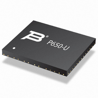
P850-G120-WH Bourns Inc., P850-G120-WH Datasheet - Page 6

P850-G120-WH
Manufacturer Part Number
P850-G120-WH
Description
SURGE SUPP TBU 100MA 850VIMP SMD
Manufacturer
Bourns Inc.
Series
TBU™r
Specifications of P850-G120-WH
Voltage - Working
425V
Technology
Mixed Technology
Number Of Circuits
2
Applications
SLIC
Package / Case
0.325" L x 0.157 " W x 0.033" H (8.25mm x 4mm x 0.85mm)
Voltage Rating
850 V
Current Rating
120 mA
Height
0.85 mm
Length
8.25 mm
Mounting
SMD/SMT
Operating Temperature Range
- 40 C to + 85 C
Termination Style
SMD/SMT
Width
4 mm
Suppressor Type
Data Line / Mains
Output Current
200mA
Peak Surge Current
200mA
Response Time
1µs
Resistance
55ohm
Operating Temperature Max
85°C
Clamping Voltage Vc Max
850V
Length/height, External
0.85mm
Rohs Compliant
Yes
External Depth
4mm
External Width
8.25mm
Lead Free Status / RoHS Status
Lead free / RoHS Compliant
Power (watts)
-
Voltage - Clamping
-
Lead Free Status / Rohs Status
Lead free / RoHS Compliant
Available stocks
Company
Part Number
Manufacturer
Quantity
Price
Part Number:
P850-G120-WH
Manufacturer:
BOURNS/伯恩斯
Quantity:
20 000
Form Factor
Impulse Voltage Rating
Directional Indication for Paired Devices
Iop Indicator
DIMENSIONS:
Device
P500-G, P850-G
Device
P500-G
P850-G
Device
P500-G
P850-G
How to Order
Packaging Specifi cations (per EIA468-B)
P = Two TBU
500 = 500 V
850 = 850 V
120 = 100 mA
200 = 200 mA
G = Bidirectional
TBU
A
3312 - 2 mm SMD Trimming Potentiometer
®
(INCHES)
®
P500-G and P850-G Protectors
MM
protectors in one device
(.165)
(.165)
(.039)
(.043)
D
Min.
Min.
4.2
4.2
1.0
1.1
K 0
A 0
(.173)
(.173)
(.047)
(.051)
Max.
Max.
4.4
4.4
1.2
1.3
B
(12.835)
(.244)
(.333)
(.311)
(.311)
Min.
Min.
8.45
Min.
326
6.2
7.9
7.9
P 500 - G 120 - WH
B 0
A
P
(13.002)
330.25
C
(.252)
(.341)
(.319)
(.319)
Max.
Max.
Max.
8.65
6.4
8.1
8.1
G (MEASURED AT HUB)
N
(.059)
(.059)
(.059)
(.159)
(.159)
Min.
Min.
Min.
K 0
1.5
1.5
1.5
3.9
3.9
t
P 0
B
D
COVER
(.098)
(.063)
(.063)
(.161)
(.161)
Max.
Max.
Max.
TAPE
TOP
2.5
B 0
1.6
1.6
4.1
4.1
Typical Part Marking
Customers should verify actual device performance in their specifi c applications.
(.504)
(.059)
(.059)
(.075)
(.075)
D
Min.
12.8
Min.
Min.
1.5
1.5
1.9
1.9
*TRANSITION FROM FULTEC TRADEMARK AND LOT CODE
MANUFACTURING
DATE CODE*
6-MONTH PERIOD CODES:
EXAMPLE: ARBC
TO BOURNS TRADEMARK AND DATE CODE IN 2009.
- 1ST DIGIT INDICATES THE YEAR’S 6-MONTH PERIOD.
- 2ND DIGIT INDICATES THE WEEK NUMBER IN THE 6-MONTH PERIOD.
- 3RD & 4TH DIGITS INDICATE SPECIFIC LOT FOR THE WEEK.
A = JAN-JUN 2009
B = JUL-DEC 2009
- 1ST DIGIT ‘A’ = JAN-JUN 2009
- 2ND DIGIT ‘R’ = WEEK 18; WEEK OF APRIL 27
- 3RD & 4TH DIGITS ‘BC’ = LOT SPECIFIC INFORMATION
D 1
P 2
A 0
C
QUANTITY: 3000 PIECES PER REEL
(.531)
(.083)
(.083)
Max.
Max.
Max.
13.5
USER DIRECTION OF FEED
2.1
2.1
PIN 1
-
-
MANUFACTURER’S
TRADEMARK*
P
C = JAN-JUN 2010
D = JUL-DEC 2010
Specifi cations are subject to change without notice.
(.795)
(.065)
(.065)
(.010)
(.010)
Min.
20.2
1.65
1.65
0.25
0.25
Min.
Min.
P 0
D
E
t
MARKING NUMBER
50GA = P500-G120-WH
50GB = P500-G200-WH
85GA = P850-G120-WH
85GB = P850-G200-WH
P 2
LINES OF
CENTER
CAVITY
(.073)
(.073)
(.014)
(.014)
Max.
Max.
Max.
1.85
1.85
0.35
0.35
-
E = JAN-JUN 2011
F = JUL-DEC 2011
D 1
(.213)
(.291)
(.461)
(.618)
(.650)
Min.
Min.
11.7
15.7
Ref.
16.5
5.4
7.4
G
EMBOSSMENT
E
W
F
F
(4.016)
(.220)
(.299)
(.484)
(.642)
W
Max.
max.
12.3
16.3
Ref.
102
5.6
7.6
N


