ZSR500N8TA Diodes Zetex, ZSR500N8TA Datasheet - Page 2
ZSR500N8TA
Manufacturer Part Number
ZSR500N8TA
Description
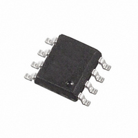
IC VOLTAGE REG 5.0V 200MA 8-SOIC
Manufacturer
Diodes Zetex
Datasheet
1.ZSR700N8TA.pdf
(18 pages)
Specifications of ZSR500N8TA
Regulator Topology
Positive Fixed
Voltage - Output
5V
Voltage - Input
7 ~ 20 V
Number Of Regulators
1
Current - Output
200mA (Max)
Operating Temperature
-55°C ~ 125°C
Mounting Type
Surface Mount
Package / Case
8-SOIC (3.9mm Width)
Lead Free Status / RoHS Status
Contains lead / RoHS non-compliant
Voltage - Dropout (typical)
-
Current - Limit (min)
-
Other names
ZSR500N8TR


ABSOLUTE MAXIMUM RATING
Input voltage
Output Current(I
Operating Temperature
Storage Temperature
ELECTRICAL CHARACTERISTICS
Notes:
1. The maximum operating input voltage and output
current of the device will be governed by the
maximum power dissipation of the selected package.
Maximum package power dissipation is specified at
25 °C and must be linearly derated to zero at
T
2. The following data represents pulse test conditions
with junction temperatures as indicated at the
initiation of the test. Continuous operation of the
devices with the stated conditions might exceed the
power dissipation limits of the chosen package.
amb
=125°C.
SERIES
ZSR285 TEST CONDITIONS (Unless otherwise stated):T
SYMBOL PARAMETER
=T
ZSR
V
V
j
=-55 to 125°C
in
V
V
V
O
V
V
l
q
l
/ V
in
O
n
q
/ T
O
O
O
o
)
Output Voltage
Line Regulation
Load Regulation
Quiescent Current
Quiescent Current
Change
Output Noise Voltage
Ripple Rejection
Input Voltage Required
To Maintain Regulation
Average Temperature
Coefficient of V
O
200mA
20V
-55 to 125°C
-65 to 150°C
CONDITIONS
I
V
I
V
I
I
I
V
f=10Hz to 10kHz
V
f=120Hz
I
O
O
O
O
O
O
in
in
in
in
=1 to 200mA
=1 to 100mA
=1 to 200mA
=1 to 100mA
=1 to 200mA
=5.0mA
=4.85 to 20V
=4.85 to 20V
=4.85 to 20V
=5.85 to 18V
2
Power Dissipation (T
SOT223
TO92
S08
3. Maximum power dissipation, for the SOT223 and
SO8 packages, is calculated assuming that the device
is mounted on a PCB measuring 2 inches square.
4. The shut down feature of the device operates if its
temperature exceeds its design limit as might occur
during external faults, short circuits etc. If the
regulator is supplied from an inductive source then a
large voltage transient, on the regulator input, can
result should the shut down circuit operate. It is
advised that a capacitor (1 F or greater) should be
applied across the regulator input to ensure that the
maximum voltage rating of the device is not
exceeded under shutdown conditions.
MIN.
2.78
2.736
2.736
48
4.85
j
=25°C, I
TYP.
2.85
10
5
2
350
75
62
4.55
0.1
600mW
780mW(Note 3)
2W(Note 3)
O
amb
=100mA, V
=25°C)
ISSUE 3 - SEPTEMBER 2001
MAX.
2.92
2.964
2.964
40
25
600
100
100
in
=6.85V
UNITS
V
V
V
mV
mV
mV
dB
V
mV/°C
A
A
A
V rms
Related parts for ZSR500N8TA
Image
Part Number
Description
Manufacturer
Datasheet
Request
R

Part Number:
Description:
DIODE ZENER 13V 500MW SOD-123
Manufacturer:
Diodes Zetex
Datasheet:

Part Number:
Description:
DIODE ZENER 13V 200MW SOD-323
Manufacturer:
Diodes Zetex
Datasheet:

Part Number:
Description:
DIODE ZENER 27V 500MW MINIMELF
Manufacturer:
Diodes Zetex
Datasheet:
Part Number:
Description:
DIODE ZENER 16V 200MW SOD-323
Manufacturer:
Diodes Zetex
Datasheet:
Part Number:
Description:
DIODE ZENER 28V 500MW SOD-123
Manufacturer:
Diodes Zetex
Datasheet:

Part Number:
Description:
DIODE ZENER 6.2V 200MW SC70-3
Manufacturer:
Diodes Zetex
Datasheet:

Part Number:
Description:
DIODE ZENER 3.6V 350MW SOT23-3
Manufacturer:
Diodes Zetex
Datasheet:

Part Number:
Description:
DIODE ZENER 4.3V 350MW SOT23-3
Manufacturer:
Diodes Zetex
Datasheet:
Part Number:
Description:
DIODE ZENER 13V 350MW SOT23-3
Manufacturer:
Diodes Zetex
Datasheet:
Part Number:
Description:
DIODE ZENER 16V 350MW SOT23-3
Manufacturer:
Diodes Zetex
Datasheet:

Part Number:
Description:
DIODE SW ARRAY 80V 200MW SOT363
Manufacturer:
Diodes Zetex
Datasheet:

Part Number:
Description:
DIODE SCHOTTKY 45V16A TO220-3
Manufacturer:
Diodes Zetex
Datasheet:
Part Number:
Description:
DIODE SCHOTTKY 45V 20A TO220-3
Manufacturer:
Diodes Zetex
Datasheet:
Part Number:
Description:
DIODE SW FAST DUAL CC SOT23-3
Manufacturer:
Diodes Zetex
Datasheet:
Part Number:
Description:
DIODE HI SPEED SW CC 70V SOT23-3
Manufacturer:
Diodes Zetex
Datasheet: