DLPA006-7 Diodes Inc, DLPA006-7 Datasheet
DLPA006-7
Specifications of DLPA006-7
Available stocks


Related parts for DLPA006-7


DLPA006-7 Summary of contents
Page 1
... Symbol θ θ STG = 25°C unless otherwise specified A Symbol Min 85 V (BR)R ⎯ ⎯ ⎯ ⎯ & & ⎯ ⎯ www.diodes.com DLPA006 / / / GND TOP VIEW Value Unit 85 60 160 mA 4.0 1.0 0.5 Value Unit 200 mW 300 mW °C/W 625 °C/W ...
Page 2
... Fig. 1 Power Derating Curve, Total Package 100 T , AMBIENT TEMPERATURE ( C) A Fig. 3 Typical Reverse Characteristics, Per Element Ordering Information (Note 7) Part Number DLPA006-7 Notes: 7. For packaging details our website at http://www.diodes.com/datasheets/ap02007.pdf. Marking Information Date Code Key Year 2005 2006 Code S T Month Jan ...
Page 3
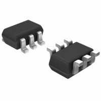
... Z Y DLPA006 Document number: DS30665 Rev BUS Ground AC 1 3-Phase AC DC source Dimensions Value (in mm www.diodes.com DLPA006 3 DC+ + Load - SOT-363 Dim Min Max A 0.10 0.30 B 1.15 1.35 C 2.00 2.20 D 0.65 Nominal F 0.30 0.40 H 1.80 2.20 ⎯ J 0.10 K 0.90 1.00 L 0.25 0.40 M ...
Page 4
... Diodes Incorporated products are not authorized for use as critical components in life support devices or systems without the expressed written approval of the President of Diodes Incorporated. DLPA006 Document number: DS30665 Rev IMPORTANT NOTICE LIFE SUPPORT www.diodes.com DLPA006 October 2008 © Diodes Incorporated ...