MC7905CD2T ON Semiconductor, MC7905CD2T Datasheet - Page 9
MC7905CD2T
Manufacturer Part Number
MC7905CD2T
Description
IC REG NEG VOLT 1A 5V D2PAK
Manufacturer
ON Semiconductor
Datasheet
1.MC7915CTG.pdf
(16 pages)
Specifications of MC7905CD2T
Regulator Topology
Negative Fixed
Voltage - Output
-5V
Voltage - Input
Down to -35V
Voltage - Dropout (typical)
1.3V @ 1A
Number Of Regulators
1
Current - Output
1A
Operating Temperature
0°C ~ 125°C
Mounting Type
Surface Mount
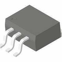
Package / Case
TO-263-2, D⊃2Pak (2 leads + Tab), TO-263AB
Polarity
Negative
Number Of Outputs
1
Output Type
Fixed
Output Voltage
- 5 V
Output Current
1 A
Line Regulation
100 mV
Load Regulation
100 mV
Input Voltage Max
- 35 V
Maximum Operating Temperature
+ 125 C
Minimum Operating Temperature
0 C
Mounting Style
SMD/SMT
Voltage Regulation Accuracy
4 %
Lead Free Status / RoHS Status
Contains lead / RoHS non-compliant
Current - Limit (min)
-
Lead Free Status / Rohs Status
Lead free / RoHS Compliant
Available stocks
Company
Part Number
Manufacturer
Quantity
Price

Part Number:
MC7905CD2T
Manufacturer:
ON/安森美
Quantity:
20 000
Part Number:
MC7905CD2TR4
Manufacturer:
ON/安森美
Quantity:
20 000


Design Considerations
designed with Thermal overload Protection that shuts down
the circuit when subjected to an excessive power overload
condition. Internal Short Circuit Protection that limits the
maximum current the circuit will pass, and Output Transistor
Safe−Area Compensation that reduces the output short circuit
current as the voltage across the pass transistor is increased.
capacitors are not required. However, it is recommended
that the regulator input be bypassed with a capacitor if the
regulator is connected to the power supply filter with long
wire lengths, or if the output load capacitance is large. An
input bypass capacitor should be selected to provide good
high−frequency characteristics to insure stable operation
under all load conditions. A 0.33 mF or larger tantalum,
mylar, or other capacitor having low internal impedance at
high frequencies should be chosen. The capacitor chosen
should have an equivalent series resistance of less than
0.7 W. The bypass capacitor should be mounted with the
shortest possible leads directly across the regulators input
terminals. Normally good construction techniques should be
used to minimize ground loops and lead resistance drops
since the regulator has no external sense lead. Bypassing the
output is also recommended.
current source when connected as above. The output current
is the sum of resistor R current and quiescent bias current as
follows:
mA. The 5.0 V regulator was chosen to minimize dissipation
and to allow the output voltage to operate to within 6.0 V
below the input voltage.
The MC7900 Series of fixed voltage regulators are
In many low current applications, compensation
The MC7905, −5.0 V regulator can be used as a constant
The quiescent current for this regulator is typically 4.3
-20 V
Input
Gnd
+
Figure 8. Current Regulator
1.0 mF
MC7905
I
O
+
5.0 V
R
) I
+
1.0 mF
B
10
R
APPLICATIONS INFORMATION
I
-
V
O
O
Gnd
= 200 mA
≤ 10 V
http://onsemi.com
9
equal to the sum of the series pass and regulator limits, which
are measured at 3.2 A and 1.8 A respectively in this case.
Series pass limiting is approximately equal to 0.6 V/R
Operation beyond this point to the peak current capability of
the MC7905C is possible if the regulator is mounted on a
heatsink; otherwise thermal shutdown will occur when the
additional load current is picked up by the regulator.
regulators may be connected as shown to obtain a dual
power supply for operational amplifiers. A clamp diode
should be used at the output of the MC7815 to prevent
potential latch−up problems whenever the output of the
positive regulator (MC7815) is drawn below ground with an
output current greater than 200 mA.
*Mounted on heatsink.
-10 V
Input
Gnd
When a boost transistor is used, short circuit currents are
The MC7815 and MC7915 positive and negative
10 mF
Gnd
+20 V
Input
0.33 mF
- 20 V
Input
+
Figure 10. Operational Amplifier Supply
(−5.0 V @ 4.0 A, with 5.0 A Current Limiting)
MJE200*
or Equiv
Figure 9. Current Boost Regulator
0.56
0.56
0.56
5.6
+
+
1.0 mF
1.0 mF
1N4001G or Equiv
1N4001G or Equiv
MC7815
MC7915
+
1.0 mF
2N3055*
or Equiv
1.0 mF
1.0 mF
MC7905*
+
+
1N4001G
1N4001G
Clamp diode
or Equiv
or Equiv
+
Output
+15 V
-15 V
Output
Gnd
1.0 mF
- 5.0 V
Output
Gnd
SC
.
Related parts for MC7905CD2T
Image
Part Number
Description
Manufacturer
Datasheet
Request
R

Part Number:
Description:
ON Semiconductor [VOLTAGE REGULATOR]
Manufacturer:
ON Semiconductor
Datasheet:
Part Number:
Description:
357-036-542-201 CARDEDGE 36POS DL .156 BLK LOPRO
Manufacturer:
ON Semiconductor
Datasheet:
Part Number:
Description:
357-036-542-201 CARDEDGE 36POS DL .156 BLK LOPRO
Manufacturer:
ON Semiconductor
Datasheet:
Part Number:
Description:
357-036-542-201 CARDEDGE 36POS DL .156 BLK LOPRO
Manufacturer:
ON Semiconductor
Datasheet:
Part Number:
Description:
357-036-542-201 CARDEDGE 36POS DL .156 BLK LOPRO
Manufacturer:
ON Semiconductor
Datasheet:
Part Number:
Description:
357-036-542-201 CARDEDGE 36POS DL .156 BLK LOPRO
Manufacturer:
ON Semiconductor
Datasheet:
Part Number:
Description:
357-036-542-201 CARDEDGE 36POS DL .156 BLK LOPRO
Manufacturer:
ON Semiconductor
Datasheet:
Part Number:
Description:
357-036-542-201 CARDEDGE 36POS DL .156 BLK LOPRO
Manufacturer:
ON Semiconductor
Datasheet:
Part Number:
Description:
357-036-542-201 CARDEDGE 36POS DL .156 BLK LOPRO
Manufacturer:
ON Semiconductor
Datasheet:
Part Number:
Description:
357-036-542-201 CARDEDGE 36POS DL .156 BLK LOPRO
Manufacturer:
ON Semiconductor
Datasheet:
Part Number:
Description:
357-036-542-201 CARDEDGE 36POS DL .156 BLK LOPRO
Manufacturer:
ON Semiconductor
Datasheet:
Part Number:
Description:
Manufacturer:
ON Semiconductor
Datasheet:
Part Number:
Description:
Manufacturer:
ON Semiconductor
Datasheet:
Part Number:
Description:
Manufacturer:
ON Semiconductor
Datasheet: