NUP2301MW6T1G ON Semiconductor, NUP2301MW6T1G Datasheet

IC TVS DIODE ARRAY 2LINE SC88

NUP2301MW6T1G

Manufacturer Part Number
NUP2301MW6T1G
Description
IC TVS DIODE ARRAY 2LINE SC88
Manufacturer
ON Semiconductor
Datasheet

Specifications of NUP2301MW6T1G

Voltage - Reverse Standoff (typ)
70V
Voltage - Breakdown
70V
Polarization
2 Channel Array - Unidirectional
Mounting Type
Surface Mount
Package / Case
SC-70-6, SC-88, SOT-363
Applications
General Purpose
Number Of Circuits
2
Voltage - Working
70V
Technology
Diode Array
Product
Standard Recovery Rectifier
Configuration
Quad
Reverse Voltage
70 V
Forward Voltage Drop
1.25 V @ 0.15 A
Forward Continuous Current
0.2 A
Max Surge Current
2 A
Reverse Current Ir
2.5 uA
Mounting Style
SMD/SMT
Lead Free Status / RoHS Status
Lead free / RoHS Compliant
Power (watts)
-
Voltage - Clamping
-
Lead Free Status / Rohs Status
Lead free / RoHS Compliant
Other names
NUP2301MW6T1GOSTR

Available stocks

Company
Part Number
Manufacturer
Quantity
Price
Part Number:
NUP2301MW6T1G
Manufacturer:
ON
Quantity:
12 000
Part Number:
NUP2301MW6T1G
Manufacturer:
ON
Quantity:
1 150
Part Number:
NUP2301MW6T1G
Manufacturer:
ON
Quantity:
30 000
Part Number:
NUP2301MW6T1G
Manufacturer:
ON/安森美
Quantity:
20 000
NUP2301MW6T1
Low Capacitance Diode
Array for ESD Protection in
Two Data Lines
provide protection for sensitive components from possible harmful
electrical transients; for example, ESD (electrostatic discharge).
Features
Applications
MAXIMUM RATINGS
 Semiconductor Components Industries, LLC, 2005
January, 2005 − Rev. 2
Maximum ratings are those values beyond which device damage can occur.
Maximum ratings applied to the device are individual stress limit values (not
normal operating conditions) and are not valid simultaneously. If these limits
are exceeded, device functional operation is not implied, damage may occur
and reliability may be affected.
1. FR−5 = 1.0  0.75  0.062 in.
Forward Current
Peak Forward Surge Current
Repetitive Peak Reverse Voltage
Average Rectified Forward
Current (Note 1)
(Averaged over any 20 ms Period)
Repetitive Peak Forward Current
Non−Repetitive Peak Forward Current
t = 1.0 ms
t = 1.0 ms
t = 1.0 S
Reverse Voltage
NUP2301MW6T1 is a MicroIntegration device designed to
Low Capacitance (2.0 pf Maximum Between I/O Lines)
Single Package Integration Design
Provides ESD Protection for JEDEC Standards JESD22
Protection for IEC61000−4−2 (Level 4)
Ensures Data Line Speed and Integrity
Fewer Components and Less Board Space
Direct the Transient to Either Positive Side or to the Ground
Pb−Free Package is Available
T1/E1 Secondary IC Protection
T3/E3 Secondary IC Protection
HDSL, IDSL Secondary IC Protection
Video Line Protection
Microcontroller Input Protection
Base Stations
I
2
C Bus Protection
Machine Model = Class C
Human Body Model = Class 3B
8.0 kV (Contact)
15 kV (Air)
Rating
(Each Diode) (T
J
= 25°C unless otherwise noted)
I
Symbol
FM(surge)
V
I
I
I
F(AV)
FRM
FSM
V
RRM
I
F
R
Value
200
500
715
450
2.0
1.0
0.5
70
70
1
mAdc
mAdc
Unit
Vdc
mA
mA
V
A
†For information on tape and reel specifications,
NUP2301MW6T1
NUP2301MW6T1G
including part orientation and tape sizes, please
refer to our Tape and Reel Packaging Specifications
Brochure, BRD8011/D.
CASE 419B
STYLE 23
6
SC−88
5
Device
4
I/O
V
V
1
ORDERING INFORMATION
N
P
2
PIN CONFIGURATION
3
http://onsemi.com
AND SCHEMATIC
3
1
2
68 = Specific Device Code
d
(Pb−Free)
Package
MARKING DIAGRAM
SC−88
SC−88
= Date Code
Publication Order Number:
NUP2301MW6T1/D
3000/Tape & Reel
3000/Tape & Reel
68
6
5
5
4
d
Shipping
N/C
I/O
N/C

Related parts for NUP2301MW6T1G

NUP2301MW6T1G Summary of contents

Page 1

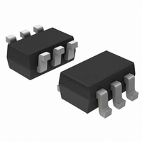
... Date Code ORDERING INFORMATION Device Package Shipping NUP2301MW6T1 SC−88 3000/Tape & Reel NUP2301MW6T1G SC−88 3000/Tape & Reel (Pb−Free) †For information on tape and reel specifications, including part orientation and tape sizes, please refer to our Tape and Reel Packaging Specifications Brochure, BRD8011/D. Publication Order Number: NUP2301MW6T1/D † ...

Page 2

THERMAL CHARACTERISTICS Characteristic Thermal Resistance Junction−to−Ambient Lead Solder Temperature Maximum 10 Seconds Duration Junction Temperature Storage Temperature ELECTRICAL CHARACTERISTICS Characteristic OFF CHARACTERISTICS Reverse Breakdown Voltage (I = 100 mA) (BR) Reverse Voltage Leakage Current Capacitance (between I/O pins) Capacitance (between ...

Page 3

... 0.0197 0.40 0.0157 *For additional information on our Pb−Free strategy and soldering details, please download the ON Semiconductor Soldering and Mounting Techniques Reference Manual, SOLDERRM/D. PACKAGE DIMENSIONS SC−88/SC70−6/SOT−363 CASE 419B−02 ISSUE 02U NOTES: 1. DIMENSIONING AND TOLERANCING PER ANSI Y14.5M, 1982. ...

Page 4

... Fax: 480−829−7709 or 800−344−3867 Toll Free USA/Canada Email: orderlit@onsemi.com N. American Technical Support: 800−282−9855 Toll Free USA/Canada Japan: ON Semiconductor, Japan Customer Focus Center 2−9−1 Kamimeguro, Meguro−ku, Tokyo, Japan 153−0051 Phone: 81−3−5773−3850 http://onsemi.com 4 ON Semiconductor Website: http://onsemi ...

Related keywords