VA100030D650DL AVX Corporation, VA100030D650DL Datasheet - Page 6
VA100030D650DL
Manufacturer Part Number
VA100030D650DL
Description
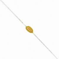
VARISTOR TVS 30VDC 120A AXIAL
Manufacturer
AVX Corporation
Series
TransGuard®r
Datasheet
1.VC040214X300WP.pdf
(10 pages)
Specifications of VA100030D650DL
Varistor Voltage
41V
Current-surge
120A
Number Of Circuits
1
Maximum Ac Volts
21VAC
Maximum Dc Volts
30VDC
Energy
0.40J
Package / Case
Axial
Product
MLV
Voltage Rating Dc
30 V
Voltage Rating Ac
21 V
Clamping Voltage
67 V
Peak Surge Current
120 A
Surge Energy Rating
0.4 J
Capacitance
550 pF
Operating Temperature Range
- 55 C to + 125 C
Mounting
Axial
Dimensions
2.54 mm Dia. x 4.32 mm L
Termination Style
Axial
Lead Free Status / RoHS Status
Lead free / RoHS non-compliant
Lead Free Status / RoHS Status
Lead free / RoHS Compliant, Lead free / RoHS non-compliant
Other names
478-2494-2


6
TransGuard
AVX Multilayer Ceramic Transient Voltage Suppressors
TYPICAL PERFORMANCE CURVES
VOLTAGE/CURRENT CHARACTERISTICS
Multilayer construction and improved grain structure result in
excellent transient clamping characteristics up to 20 amps
peak current, while maintaining very low leakage currents
under DC operating conditions. The VI curves below show the
voltage/current characteristics for the 5.6V, 9V, 14V, 18V and
low capacitance StaticGuard parts with currents ranging from
parts of a micro amp to tens of amps.
PEAK POWER VS PULSE DURATION
100
80
60
40
20
0
10
1300
1200
1100
1000
-9
900
800
700
600
500
400
300
200
100
0
10
10
-7
VC04LC18V500
VC040218X400
VC040214X300
VC040209X200
VC040205X150
10
IMPULSE DURATION (μS)
-5
10
Current (A)
-3
100
VC040218X400
VC040214X300
VC040209X200
VC04LC18V500
VC040205X150
®
10
-1
10
1000
10
3
(0402 CHIP SIZE)
10
5
ESD TEST OF 0402 PARTS
INSERTION LOSS CHARACTERISTICS
PULSE DEGRADATION
Traditionally varistors have suffered degradation of electrical
performance with repeated high current pulses resulting in
decreased breakdown voltage and increased leakage cur-
rent. It has been suggested that irregular intergranular
boundaries and bulk material result in restricted current
paths and other non-Schottky barrier paralleled conduction
paths in the ceramic. Repeated pulsing of TransGuard
sient voltage suppressors with 150Amp peak 8 x 20μS
waveforms shows negligible degradation in breakdown
voltage and minimal increases in leakage current. This
does not mean that TransGuard
degradation, but it occurs at much higher current.
-10
-15
-20
-25
-5
0.01
0
VC04LC18V
VC040218X
VC040214X
VC040209X
VC040205X
35
30
25
20
15
10
5
10
VC04LC18V500
VC040218X400
VC040214X300
VC040209X200
VC040205X150
0.1
100
8kV ESD STRIKES
Frequency (GHz)
®
suppressors do not suffer
1000
1
10000
®
10
tran-
Related parts for VA100030D650DL
Image
Part Number
Description
Manufacturer
Datasheet
Request
R

Part Number:
Description:
Manufacturer:
AVX Corporation
Datasheet:
Part Number:
Description:
Manufacturer:
AVX Corporation
Datasheet:
Part Number:
Description:
Manufacturer:
AVX Corporation
Datasheet:
Part Number:
Description:
Manufacturer:
AVX Corporation
Datasheet:
Part Number:
Description:
Manufacturer:
AVX Corporation
Datasheet: