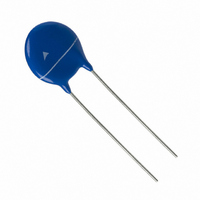
S14K30G5S5 EPCOS Inc, S14K30G5S5 Datasheet - Page 19

S14K30G5S5
Manufacturer Part Number
S14K30G5S5
Description
VARISTOR 30VRMS 14MM RADIAL TR
Manufacturer
EPCOS Inc
Series
StandarDr
Datasheet
1.S05K140.pdf
(36 pages)
Specifications of S14K30G5S5
Varistor Voltage
47V
Current-surge
1.0kA
Number Of Circuits
1
Maximum Ac Volts
30VAC
Maximum Dc Volts
38VDC
Energy
9.0J
Package / Case
Disc 14mm
Lead Free Status / RoHS Status
Lead free / RoHS Compliant
Other names
B72214S 300K551
B72214S0300K551
B72214S300K551
B72214S0300K551
B72214S300K551
Reliability data
Test
Climatic sequence
Fast temperature cycling
Damp heat, steady state
Solderability
Please read Cautions and warnings and
Important notes at the end of this document.
Test methods/conditions
CECC 42 000, test 4.16
The specimen shall be subjected to:
a) dry heat at UCT, 16 h
b) damp heat, 1st cycle:
c) cold, LCT, 2 h
d) damp heat, additional 5 cycles:
Then the specimen shall be stored at
room temperature and normal humidity
for 1 to 2 h.
Thereafter, the change of V
measured. Thereafter, insulation resis-
tance R
to CECC 42 000, test 4.8 at V = 500 V.
IEC 60068-2-14, test Na, LCT/UCT,
dwell time 30 min, 5 cycles
The specimen shall be subjected to
40 ±2 °C, 90 to 95% r. H. for 56 days
without load / with 10% of the maximum
continuous DC operating voltage V
Then stored at room temperature and
normal humidity for 1 to 2 h.
Thereafter, the change of V
measured. Thereafter, insulation resis-
tance R
to CECC 42 000, test 4.8 at V = 500 V.
IEC 60068-2-20, test Ta,
method 1 with modified conditions for
lead-free solder alloys: 245 °C, 3 s:
After dipping the terminals to a depth
of approximately 3 mm from the body
in a soldering bath of 245 °C for 3 s, the
terminals shall be visually examined.
55 °C, 93% r. H., 24 h
55 °C/25 °C, 93% r. H., 24 h/cycle.
ins
ins
shall be measured according
shall be measured according
19
11/07
v
v
shall be
shall be
Leaded varistors
StandarD series
DC
.
Requirement
|
R
|
No visible damage
|
R
The inspection shall be
carried out under adequate
light with normal eyesight or
with the assistance of a
magnifier capable of giving
a magnification of 4 to
10 times. The dipped sur-
face shall be covered with
a smooth and bright solder
coating with no more than
small amounts of scattered
imperfections such as
pinholes or un-wetted or
de-wetted areas. These
imperfections shall not be
concentrated in one area.
∆V/V (1 mA)
∆V/V (1 mA)
∆V/V (1 mA)
ins
ins
≥1 MΩ
≥1 MΩ
|
|
|
≤10%
≤5%
≤10%


