V250LA20C Littelfuse Inc, V250LA20C Datasheet
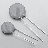
VARISTOR 250V C-III 14MM RADIAL

V250LA20C

Manufacturer Part Number
V250LA20C
Description
VARISTOR 250V C-III 14MM RADIAL
Manufacturer
Littelfuse Inc
Series
C-IIIr
Datasheets

Specifications of V250LA20C

Energy
135J
Varistor Voltage
429V
Current-surge
5kA
Number Of Circuits
1
Maximum Ac Volts
250VAC
Package / Case
Disc 14mm
Technology
Metal Oxide
Clamping Current
50A
Clamping Voltage
650V
Lead Style
Radial
Ac Voltage Rating (max)
250VAC
Operating Temp Range
-55C to 85C
Mounting
Through Hole
Surge Current (max)
6000A
Lead Spacing
8.5mm
Product Depth (mm)
7.3mm
Product Height (mm)
20mm
Product Diameter (mm)
17mm
Product
MOV
Voltage Rating Dc
429 V
Voltage Rating Ac
250 V
Peak Surge Current
6 KA
Operating Temperature Range
- 55 C to + 85 C
Dimensions
14 mm Dia.
Termination Style
Radial
Lead Free Status / RoHS Status
Lead free / RoHS Compliant
Maximum Dc Volts
-
Lead Free Status / Rohs Status
Lead free / RoHS Compliant
©2009 Littelfuse, Inc.
Specifications are subject to change without notice.
Please refer to www.littelfuse.com/series/c-iii.html for current information.
RoHS
Continuous
Steady State Applied Voltage:
Transients:
Temperature Coefficient (a
Agency Approvals
Absolute Maximum Ratings
CAUTION: Stresses above those listed in "Absolute Maximum Ratings" may cause permanent damage to the device. This is a stress only
rating and operation of the device at these or any other conditions above those indicated in the operational sections of this specification is
not implied.
Agency
C-III Varistor Series
Single-Pulse Peak Current (I
(See Peak Pulse Current Test Waveform)
V
) of Clamping Voltage (V
STG
TM
)
Agency File Number
42201-006
116895E
A
E75961
)
)
TM
C
) at Specified Test Current
) 8/20μs Wave
Varistor Products
Radial Lead Varistors > C-III series
Revision: June 3, 2009
101
Description
The C-III Series of Metal-Oxide Varistors (MOVs) are
specifically designed for applications requiring high surge
energy absorption ratings and superior multiple pulse
absorption rating. This is achieved through a special
dielectric material formulation which also results in
higher repetitive surge ratings than other MOV types.
The C-III Series is primarily intended for use in AC
line Transient Voltage Surge Suppressor (TVSS)
product environment and other similar applications
requiring high transient energy and peak current
capability in a relatively small package size.
Features
compliant option
available. Please see
the device and ratings
specifications table
for more information
absorption capability
W
current capability
I
9000A (8/20μs)
TM
gh energy
TM
3500A to
40J to 530J (2ms)
3500 to 9000
C-III Series
-55 to +125
130 to 660
-55 to +85
40 to 530
5000
1000
<0.0
Units
%/ºC
ºC
ºC
A
V
J
V
Wide operating
voltage range
V
reel for automatic
insertion; Also available
with crimped and/or
trimmed lead styles
85ºC ambient
The C-III Series is
supplied in 10mm,
14mm and 20mm
disc versions with
various lead options
130V to 680V
C-III Varistor Series

Related parts for V250LA20C

V250LA20C Summary of contents

Page 1

C-III Varistor Series RoHS Agency Approvals Agency Agency File Number E75961 116895E 42201-006 Absolute Maximum Ratings Continuous Steady State Applied Voltage: ) Transients: Single-Pulse Peak Current (I TM (See Peak Pulse Current Test Waveform STG Temperature ...

Page 2

C-III Series Ratings Lead–free and RoHS Compliant Standard Models Models Part Number Branding Part Number C-III Varistor Series Varistor Products Radial Lead Varistors > C-III series Continuous Maximum V Branding V Energy (2ms)W M(AC) (V) 130 130 130 130 140 ...

Page 3

C-III Series Specifications Lead–free And RoHS Compliant Standard Models Models Diameter (mm) Part Number Part Number 1 Average power dissipation of transients not to exceed 0.6W and 1W for model sizes 14mm and 20mm, respectively. 2 7mm parts also available-contact ...

Page 4

Power Dissipation Ratings Should transients occur in rapid succession, the average power dissipation is the energy (watt-seconds) per pulse times the number of pulses per second. The power so developed must be within the specifications shown on the device. The ...

Page 5

... Transient V-I Characteristics Curves (continued) Maximum Clamping Voltage for 14mm Parts V130LA10C(P) – V420LA20C(P) 10,000 MODEL SIZE = 60LA20C(P) V 20LA20C(P) V385LA20C(P) V320LA20C(P) V300LA20C(P) V275LA20C(P) 1,000 V250LA20C(P) V1 0LA10C(P) V130LA10C(P) 100 0.001 0.01 0.1 1 1.0 Figure Peak Amperes (A) Maximum Clamping Voltage for 20mm Parts ...

Page 6

Wave Solder Profile Non Lead–free Profile 300 Maximum Wave 240C 250 200 150 100 0.5 1 1.5 2 2.5 Figure 10 TIME(MINUTES) Physical Specifications Lead Material Soldering Characteristics Method 208E Cured, flame retardant epoxy polymer Insulating Material ...

Page 7

AC Bias Reliability The C-III Series MOVs were designed for use on the AC line. The varistor is connected across the AC line and is biased with a constant amplitude sinusoidal voltage. It should be noted that the definition of ...

Page 8

Product Dimensions (mm) ØD A 25.4 (1.00) Øb CRIMPED AND TRIMMED LEADS CRIMPED AND TRIMMED LEAD e crimp and trimmed leads. This option is supplied to the dimensions shown below *Seating plane interpretation per IEC-60717 V Voltage ...

Page 9

Tape and Reel Specifications SEATING H 1 PLANE ...

Page 10

Part Numbering System BASE PART CODES (See Ratings & Specifications tables and notes below) V XXXX LA For “VARISTOR” V M(AC) (Three or four digits -- 130V to 1,000V) SERIES + PACKAGING / LEAD STYLE DESIGNATOR (See BASE PART CODES ...

Related keywords