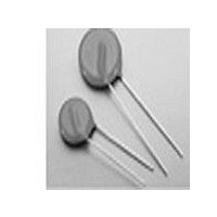
VE07M00151KDD AVX Corporation, VE07M00151KDD Datasheet - Page 2

VE07M00151KDD
Manufacturer Part Number
VE07M00151KDD
Description
MOV 150V RMS 7MM RADIAL
Manufacturer
AVX Corporation
Datasheet
1.VE07M00141K.pdf
(13 pages)
Specifications of VE07M00151KDD
Energy
4.9J
Varistor Voltage
240V
Current-surge
400A
Number Of Circuits
1
Maximum Ac Volts
150VAC
Maximum Dc Volts
200VDC
Package / Case
Disc 7mm
Technology
Zinc Oxide
Capacitance Value
80pF
Clamping Current
5A
Clamping Voltage
400V
Lead Style
Radial
Ac Voltage Rating (max)
150VAC
Dc Voltage Rating (max)
200VDC
Mounting
Through Hole
Surge Current (max)
400A
Lead Spacing
5.08mm
Product Depth (mm)
4.3mm
Product Height (mm)
10mm
Product Diameter (mm)
7mm
Product
MOV
Voltage Rating Dc
200 V
Voltage Rating Ac
150 V
Peak Surge Current
400 A
Capacitance
80 pF
Operating Temperature Range
- 40 C to + 125 C
Lead Free Status / RoHS Status
Contains lead / RoHS non-compliant
Lead Free Status / RoHS Status
Compliant, Contains lead / RoHS non-compliant
Zinc Oxide Varistors
VE 07/09/13/17/24
DIMENSIONS
* VE13 / VF10: For models with V
**VE24 / VF20: For lead diameter = 1.0 (.039),
VE07
VE09
VE13* VF10* 10 (.393) 13* (.512) 16 (.630) see
VE17
VE24** VF20** 20 (.787) 24 (.945) 27 (1.06)
Type
110
110
110
110
135
135
135
135
135
135
135
135
voltage (8 x 20 µs)
Vp (V)
43
43
43
43
53
53
53
53
65
65
65
65
77
77
77
77
93
93
93
93
Max. clamping
VF05
VF07
VF14 14 (.551) 17 (.669) 20 (.787) table 0.8 (.031) 7.62 (0.30)
Type
10
10
10
10
10
10
10
10
25
50
Ip (A)
1
2.5
5
1
2.5
5
1
2.5
5
1
2.5
5
1
2.5
5
1
2.5
5
1
2.5
5
5
diameter diameter
Ceramic
5 (.196)
7 (.275)
other version/suffixes available with:
E = 5.08 (0.20) Suffix:
Ø = 0.6 (.024) Bulk: HB
D = 12.5 (.492) max Tape: DA, DB, DC,
please consult us.
D
Max. energy absorption
Maximum
7 (.275) 10 (.394)
9 (.354) 12 (.472)
coated
10.0
13.0
15.0
Number of surges
millimeters (inches)
0.4
0.9
2
4
0.5
1.1
2.5
4.7
0.6
1.3
3.1
5.7
0.7
1.6
3.7
7
0.9
2.0
4.4
9.0
1.1
2.5
5.4
1.3
3.0
8.4
1.8
4.2
8.4
1
(10 x 1000 µs)
W (J)
max.
H
RMS
11
10
0.2
0.6
1.3
2.6
0.3
0.7
1.6
3.0
0.3
0.9
2.0
4.0
0.4
1.0
3
5
0.4
1
4
7
0.4
1
4.4
8
0.5
1
5.9
8.5
0.6
1.6
6
320 V
max. –0.05 (.002) ± 0.8 (.031)
t
0.6 (.024) 5.08 (0.20)
0.6 (.024) 5.08 (0.20)
0.8* (.031) 7.62*(0.30)
0.8** (.031) 7.62 (0.30)
DD, DQ, ...
VF 05/07/10/14/20
1 surge
1000
1000
1000
1000
1000
1000
1000
1200
2500
4500
+10%
Max. permissible
100
250
500
100
250
500
100
250
500
100
250
500
100
250
500
100
250
500
100
250
500
400
ø
peak current
(8 x 20 µs)
Ip (A)
2 surges
1250
2500
E
125
250
500
125
250
500
125
250
500
125
250
500
125
250
500
125
250
500
125
250
500
200
600
50
50
50
50
50
50
50
capacitance
GENERAL CHARACTERISTICS
Type
AC nominal voltage (EIA coding) for VE types
V
Logo
UL logo (when approved)
Lot number (VE13/17/24 and VF10/14/20 only)
Storage temperature:
Max. operating temperature: +85°C
Response time:
Voltage coefficient temp.:
Voltage proof:
Epoxy coating:
MARKING
1mA
f = 1kHz
1050
1900
4000
4000
1050
1900
4000
6800
1500
3100
5700
1250
2800
4600
1050
2150
3500
1900
3100
1700
2800
1800
Typical
750
660
580
460
850
400
720
300
530
950
pF
varistor voltage (EIA coding) for VF types
dissipation
power
Mean
0.01
0.02
0.05
0.10
0.01
0.02
0.05
0.10
0.01
0.02
0.05
0.10
0.01
0.02
0.05
0.10
0.01
0.02
0.05
0.10
0.01
0.02
0.05
0.10
0.01
0.02
0.05
0.10
0.1
0.2
0.4
0.6
W
mm (inches)
3.6 (.142)
3.6 (.142)
4.3 (.169)
4.3 (.169)
3.7 (.146)
3.7 (.146)
4.3 (.169)
4.3 (.169)
3.9 (.154)
3.9 (.154)
4.5 (.177)
4.5 (.177)
3.6 (.142)
3.6 (.142)
4.4 (.173)
4.4 (.173)
3.8 (.150)
3.8 (.150)
4.4 (.173)
4.4 (.173)
3.9 (.154)
3.9 (.154)
4.7 (.185)
4.7 (.185)
4.1 (.161)
4.1 (.161)
4.9 (.193)
4.9 (.193)
3.5 (.138)
3.5 (.138)
4.1 (.161)
4.1 (.161)
Maximum
thickness
t
-40°C to +125°C
< 25 ns
⎮K⎮ < 0.09%/°C
2500 V
Flame retardant
UL94-VO
characteristic
Page
22
22
22
23
22
22
22
23
22
22
22
23
22
22
22
23
22
22
22
23
22
22
22
23
22
22
22
23
22
22
22
23
V/I
Derating
curves
Page
24
25
26
27
24
25
26
27
24
25
26
27
24
25
26
27
24
25
26
27
24
25
26
27
24
25
26
27
24
25
26
27
13


