2891314 Phoenix Contact, 2891314 Datasheet - Page 8
2891314
Manufacturer Part Number
2891314
Description
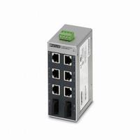
SWITCH ETHERNET 6/RJ45-2SC F/OPT
Manufacturer
Phoenix Contact
Type
Ethernetr
Specifications of 2891314
Features
6 Ports
Product
Switches
Usoc Codes
RJ45
Number Of Ports
6, 2
Gender
Female
Shielding
Shielded
Current Rating
230 mA
Voltage Rating
24 V
Housing Material
Aluminum
Contact Material
Copper Alloy
Contact Type
RJ45, Fiber Optic
Number Of Rows
2
Operating Temperature Range
0 C to + 60 C
Phoenix Part Number
FL SWITCH SFN 6TX/2FX
Lead Free Status / RoHS Status
Lead free / RoHS Compliant


5.5
5.6
6
2732_en_A
1000/ACT
100/ACT
LNK/ACT
Data Transmission Speed LEDs
(10/100/1000 Mbps Switches)
Data Transmission Speed LEDs (2 LEDs/Port)
Installation
100
One LED/port ON or blinking:
Both LEDs/port ON or blinking:
LNK/ACT LED:
ON: indicates an electrical link
Flashing: indicates network traffic (at high data
rates the blinking is in a constant rate)
CAUTION:
Only qualified personnel may start up and operate
this device. Qualified personnel are persons
authorized to start up, ground and mark devices,
systems, and equipment according to the
standards of safety technology.
NOTE:
The FL SWITCH SFN… module is designed for
SELV and PELV operation according to
IEC 61140/EN 61140.
ON: indicates an electrical link
Flashing: indicates network traffic at the data
rate (x Mbps)
Both ON: indicates a 10 Mbps electrical link
Both flashing: indicates network traffic at
10 Mbps)
ON/blinking
ON/blinking
10 Mbps
ON/blinking
10 Mbps
OFF
ON/blinking
ON/blinking
100 Mbps
ON/blinking
100 Mbps
1000 Mbps
ON/blinking
ON
OFF
Install the FL SWITCH SFN… on a clean DIN rail. To avoid
contact resistance use only clean, corrosion-free rails that
meet the EN 50022 standard. End clamps should be
mounted on both sides of the module to stop the modules
from slipping on the rail.
6.1
1.
2.
3.
6.2
1.
2.
3.
6.3
The switch is designed for SELV and PELV operation at
+24 V DC according to IEC 61140/EN 61140. Only SELV
and PELV according to the defined standards may be used
for supply purposes.
Snapping the switch onto a grounded DIN rail connects it to
the ground potential. In an environment particularly prone to
Place the module onto the DIN rail from above. The
upper holding keyway must be hooked onto the top
edge of the DIN rail.
Push the module from the front towards the mounting
surface.
Once the module has been snapped on properly, check
that it is fixed securely on the rail.
Insert a suitable tool (e.g., needle-nose pliers) into the
arresting latch and pull it down.
Pull the module slightly away from the mounting
surface.
Lift the module from the rail.
Assembly
Removal
Power Connection
WARNING:
A.)THIS EQUIPMENT IS SUITABLE FOR USE IN
CLASS I, ZONE 2, GROUPS A, B, C, AND D OR
NON- HAZARDOUS LOCATIONS ONLY.
B.) WARNING - EXPLOSION HAZARD -
SUBSTITUTION OF COMPONENTS MAY
IMPAIR SUITABILITY FOR CLASS I, ZONE 2.
C.) WARNING - EXPLOSION HAZARD - DO
NOT DISCONNECT EQUIPMENT UNLESS
POWER HAS BEEN SWITCHED OFF OR THE
AREA IS KNOWN TO BE NON-HAZARDOUS.
NOTE:
Connect the DIN rail to protective earth ground
using a grounding terminal block. The modules
are grounded when they are snapped onto the
rail. Connect protective earth ground with low
impedance. 1000 Mbps switches have a
protective ground connecting screw on top.
PHOENIX CONTACT
FL SWITCH SFN…
8
Related parts for 2891314
Image
Part Number
Description
Manufacturer
Datasheet
Request
R

Part Number:
Description:
PHOENIX CONTACT
Manufacturer:
Phoenix Contact
Datasheet:

Part Number:
Description:
PHOENIX CONTACT P/N 27 53 50 4 BUS TERMINAL MOD ULE WITH RE MOTE BUS BRANC
Manufacturer:
Phoenix Contact

Part Number:
Description:
PHOENIX CONTACT
Manufacturer:
Phoenix Contact
Datasheet:

Part Number:
Description:
PHOENIX CONTACT
Manufacturer:
Phoenix Contact
Datasheet:

Part Number:
Description:
PHOENIX CONTACT
Manufacturer:
Phoenix Contact
Datasheet:
Part Number:
Description:
PHOENIX CONTACT
Manufacturer:
Phoenix Contact
Datasheet:
Part Number:
Description:
SIDE ELEMENT
Manufacturer:
Phoenix Contact
Datasheet:

Part Number:
Description:
CONN TERM BLOCK 2.54MM 8POS
Manufacturer:
Phoenix Contact
Datasheet:

Part Number:
Description:
VOLT REGULATOR MODULE 24VDC 1A
Manufacturer:
Phoenix Contact
Datasheet:

Part Number:
Description:
VOLT REGULATOR MODULE 24VDC 2A
Manufacturer:
Phoenix Contact
Datasheet: