RES 2.2K OHM CARBON FILM 1/4W 5%


ERD-S2TJ222V

Manufacturer Part NumberERD-S2TJ222V
DescriptionRES 2.2K OHM CARBON FILM 1/4W 5%
ManufacturerPanasonic - ECG
SeriesERDS2
ERD-S2TJ222V datasheets

Availability: By request

International delivery:

Warranty: 60 days

Shipping & payment terms

Added to cart


Specifications of ERD-S2TJ222V

Resistance (ohms)2.2KPower (watts)0.25W, 1/4W
CompositionCarbon FilmTemperature Coefficient-150/ -350ppm/°C
Tolerance±5%Size / Dimension0.067" Dia x 0.126" L (1.70mm x 3.20mm)
Lead StyleThrough HolePackage / CaseAxial
Resistance In Ohms2.20KCaseAxial
Lead Free Status / RoHS StatusLead free / RoHS CompliantFeatures-
Height-Other namesERDS2TJ222V
P2.2KBATB
1
Page 1
2
Page 2
3
Page 3
4
Page 4
5
Page 5
6
Page 6
7
Page 7
Page 1/7

Download datasheet (216Kb)Embed
Next
Carbon Film Re sis tors
ERDS1
(0.5 W)
Type:
ERDS2
(0.25 W)
ERD25
(0.25 W)
Features
● Reliability .................... High reliability by using carbon fi lm
● Automatic insertion .... Taping style for automatic inserting machines
● Marking ...................... 4 color code marking
● Flame Retardant ........ Using UL 94 V-0 approved coating for fl ame retardant type
● Reference Standard ... IEC 60115-2, JIS C 5201-2
Explanation of Part Numbers
1
2
3
E
R
D
Product
Power Rating
at 70 °C Amb.
Code
Carbon
S1
0.5 W
T
Film
S2
0.25 W
V, FV
Resistors
25
0.25 W
F
Construction
Primary coating
Spiralling
Carbon film
(Metal film for 4.3
or less)
High thermal
conductive ceramic
core
End cap
Design and specifi cations are each subject to change without notice. Ask factory for the current technical specifi cations before purchase and/or use.
Should a safety concern arise regarding this product, please be sure to contact us immediately.
Discontinued
4
5
6
7
S
1
T
J
Special Feature and/or
Resistance
Cut & Formed Style (Type)
Tolerance
Standard (Straight leads)
J
Radial formed (S1, 25)
Jumper
0
Flame-retardant
Dimensions in mm (not to scale)
Lead wire
1st significant figure.
2nd significant figure.
Multiplier
Tolerance
Insulative
coating
Standard:
Epoxy resin
Type
Flame retardant
Silicone resin
(UL94V-0
ERDS1T
approved)
ERDS1F
ERDS2T
ERDS2F
ERD25T
Marking
ERD25F
Carbon Film Resistors
8
9
10
11
1
0
3
T
Resistance Value
Suffix for Packaging and
/or Cut & Formed Leads
The first two digits are
±5 %
significant figures of
Standard bulk
Nil
resistance and the third
packing
one denotes number of
Standard taped
zeros following.
box (26 mm axial
T
Decimal point expres-
or Radial)
sed by R as 4.7 = 4R7.
Standard taped
(*Nil for Jumper)
V
& box (52 mm axial)
Lead formed
P
Flame retardant
H
L
H
fd
See Page ER131 for color code indication
Standard Quantity : 2000 pcs.
Dimensions (mm)
fD
fd
L
H
+0.65
+0.50
±0.05
6.35
2.30
0.60
20 min.
–0.35
–0.30
±0.20
+0.20
±0.05
3.20
1.70
0.45
20 min.
–0.10
+0.65
+0.50
±0.05
6.35
2.30
0.60
20 min.
–0.35
–0.30
fD
Mass
(Weight)
[mg/pc.]
228
107
228
Feb. 2006

ERD-S2TJ222V Summary of contents

  • Page 1

    ... Multiplier Tolerance Insulative coating Standard: Epoxy resin Type Flame retardant Silicone resin (UL94V-0 ERDS1T approved) ERDS1F ERDS2T ERDS2F ERD25T Marking ERD25F Carbon Film Resistors Resistance Value Suffix for Packaging and /or Cut & Formed Leads The first two digits are ± ...

  • Page 2

    ... Overload (Short-time Overload) Test Voltage (SOTV) shall be determined from SOTV=2.5 Power Rating or max. Overload Voltage list ed above which ev er less. (3) Intermittent Overload Test Voltage (IOTV) shall be determined from IOTV=4 Power Rating (IOTV=3 Power Rating for ERDS2 type) or max. Intermittent Overload Voltage list ed above which ev er less ...

  • Page 3

    ... Std. Qty. Type Part Numbers (pcs./box) ERDS2TJ T Carbon 5000 Film R ERDS2FJ T ERDS2TJ V Carbon 5000 Film R ERDS2FJ V ERD25TJ T ERD25FJ T Carbon 4000 Film R ERDS1TJ T ERDS1FJ T ERD25TJ V ERD25FJ V Carbon 2000 Film R ERDS1TJ V ERDS1FJ V d 0.45 0 +2.0 6.0 0.6 –1 ...

  • Page 4

    ... ERDS1FVJ T ERD25FVJ T Dimensions (mm max. t 0.7±0.2 g 0±2.5 ° h 0±2 +0.65 A 6.35 –0.35 +0.5 fD 2.3 –0.3 fd 0.60±0.05 Std. Qty. Part Numbers (pcs.) ERDS2TYJ T 2000 Dimensions (mm) h 0±2 t 0.7±0.2 A 3.2±0.2 +0.2 fD 1.7 –0.1 fd 0.45±0.05 Feb. 2006 ...

  • Page 5

    ... When applying pulses to the resistors, keep the pulse peak within the rated voltage. 3. When the resistors' protective coatings are chipped, fl awed, or removed, the char ac ter is tics of the resistors may be impaired. Take special care not to apply mechanical shock during automatic mounting or cause dam age during handling of the boards with the resistors mounted ...

  • Page 6

    ... Safety Precautions (Common precautions for Fixed Resistors) • When using our products, no matter what sort of equipment they might be used for, be sure to make a written agreement on the specifi cations with us in advance. The design and specifi cations in this catalog are subject to change without prior notice. • ...

  • Page 7

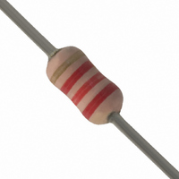
    ... Tolerance Code ■ Color code indication for the resistance value and the tolerance Fixed resistors whose resistance value and tolerance are indicated by color code follow the stan dard below. Color code Color First digit Black 0 Brown 1 Red 2 Orange 3 Yellow ...