PR03000201000JAC00 Vishay, PR03000201000JAC00 Datasheet - Page 9
PR03000201000JAC00
Manufacturer Part Number
PR03000201000JAC00
Description
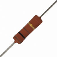
RES 100 OHM METAL FILM 3W 5%
Manufacturer
Vishay
Series
PR03r
Type
Power Metal Film Resistorr
Datasheet
1.PR01000101004JR500.pdf
(16 pages)
Specifications of PR03000201000JAC00
Temperature Coefficient
±250ppm/°C
Resistance (ohms)
100
Power (watts)
3W
Composition
Metal Film
Features
Flame Retardant Coating
Tolerance
±5%
Size / Dimension
0.205" Dia x 0.768" L (5.20mm x 19.50mm)
Lead Style
Through Hole
Package / Case
Axial
Resistance In Ohms
100
Case
Axial
Resistance
100ohm
Resistance Tolerance
± 5%
Power Rating
3W
Voltage Rating
750V
Resistor Element Material
Metal Film
Termination Style
Axial
Operating Temperature Range
- 55 C to + 155 C
Dimensions
5.2 mm Dia. x 16.7 mm L
Power Rating(s)
3W
Tolerance (+ Or -)
5%
Operating Temp Range
-55C to 155C
Case Style
Conformal
Failure Rate
Not Required
Lead Spacing (nom)
Not Requiredmm
Product Length (mm)
19.5mm
Product Depth (mm)
Not Requiredmm
Product Height (mm)
Not Requiredmm
Construction
Cylindrical
Lead Free Status / RoHS Status
Lead free / RoHS Compliant
Height
-
Lead Free Status / Rohs Status
Details
Other names
2322 195 14101
232219514101
5093NW100R0J
5093NW100R0JA8AFX
5093NW100R0JBC
BC100W-3JTB
BC100W-3JTB
PPC100W-3JTB
232219514101
5093NW100R0J
5093NW100R0JA8AFX
5093NW100R0JBC
BC100W-3JTB
BC100W-3JTB
PPC100W-3JTB


PR01/02/03
Vishay BCcomponents
Ø 0.6 mm Cu-leads
Minimum distance from resistor body to PCB = 1 mm
Application Information
www.vishay.com
118
PR01 Temperature rise (ΔT) at the lead end (soldering point) as a
conditions; the data may deviate according to the applications.
conditions; the data may deviate according to the applications.
This graph is based on measured data under constant voltage
This graph is based on measured data under constant voltage
function of dissipated power at various lead lengths after mounting.
PR02 Time to interruption as a function of overload power
PR03 Time to interruption as a function of overload power
(K)
∆ T
(s)
(s)
10
10
10
10
t
t
100
10
10
-1
1
-1
1
80
60
40
20
2
2
0
0
0
0
for range: 0.68 R ≤ R
for range: 5 R ≤ R
20
50
40
0.4
100
60
150
n
For technical questions, contact:
n
< 68 R
80
0.8
≤ 560 R
P
P
overload
overload
Power Metal Film Leaded Resistors
200
P (W)
100
15 mm
25 mm
20 mm
(W)
(W)
120
250
1.2
filmresistorsleaded@vishay.com
Interruption Characteristics
Ø 0.6 mm Cu-leads
Ø 0.6 mm FeCu-leads
conditions; the data may deviate according to the applications.
This graph is based on measured data under constant voltage
PR02 Time to interruption as a function of overload power
PR01 Hot-spot temperature rise (ΔT) as a function
PR01 Hot-spot temperature rise (ΔT) as a function
∆ T
(K)
∆ T
(K)
10
(s)
10
t
200
160
120
10
200
160
120
-1
1
80
40
80
40
2
0
0
0
0
0
for range: 68 R ≤ R
20
of dissipated power.
of dissipated power.
40
0.4
0.4
60
n
80
≤ 560 R
0.8
Document Number: 28729
0.8
P
overload
100
P (W)
P (W)
Revision: 14-Oct-09
(W)
120
1.2
1.2
Related parts for PR03000201000JAC00
Image
Part Number
Description
Manufacturer
Datasheet
Request
R

Part Number:
Description:
357-036-542-201 CARDEDGE 36POS DL .156 BLK LOPRO
Manufacturer:
Vishay
Datasheet:
Part Number:
Description:
357-036-542-201 CARDEDGE 36POS DL .156 BLK LOPRO
Manufacturer:
Vishay
Datasheet:
Part Number:
Description:
357-036-542-201 CARDEDGE 36POS DL .156 BLK LOPRO
Manufacturer:
Vishay
Datasheet:
Part Number:
Description:
357-036-542-201 CARDEDGE 36POS DL .156 BLK LOPRO
Manufacturer:
Vishay
Datasheet:
Part Number:
Description:
357-036-542-201 CARDEDGE 36POS DL .156 BLK LOPRO
Manufacturer:
Vishay
Datasheet:
Part Number:
Description:
357-036-542-201 CARDEDGE 36POS DL .156 BLK LOPRO
Manufacturer:
Vishay
Datasheet:
Part Number:
Description:
357-036-542-201 CARDEDGE 36POS DL .156 BLK LOPRO
Manufacturer:
Vishay
Datasheet:
Part Number:
Description:
357-036-542-201 CARDEDGE 36POS DL .156 BLK LOPRO
Manufacturer:
Vishay
Datasheet:
Part Number:
Description:
357-036-542-201 CARDEDGE 36POS DL .156 BLK LOPRO
Manufacturer:
Vishay
Datasheet:
Part Number:
Description:
357-036-542-201 CARDEDGE 36POS DL .156 BLK LOPRO
Manufacturer:
Vishay
Datasheet:
Part Number:
Description:
357-036-542-201 CARDEDGE 36POS DL .156 BLK LOPRO
Manufacturer:
Vishay
Datasheet:
Part Number:
Description:
357-036-542-201 CARDEDGE 36POS DL .156 BLK LOPRO
Manufacturer:
Vishay
Datasheet:
Part Number:
Description:
357-036-542-201 CARDEDGE 36POS DL .156 BLK LOPRO
Manufacturer:
Vishay
Datasheet:
Part Number:
Description:
357-036-542-201 CARDEDGE 36POS DL .156 BLK LOPRO
Manufacturer:
Vishay
Datasheet:
Part Number:
Description:
357-036-542-201 CARDEDGE 36POS DL .156 BLK LOPRO
Manufacturer:
Vishay
Datasheet: