MP930-1.00-1% Caddock Electronics Inc, MP930-1.00-1% Datasheet - Page 2
MP930-1.00-1%
Manufacturer Part Number
MP930-1.00-1%
Description
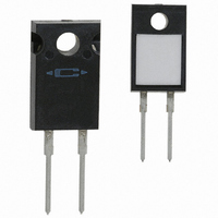
RESISTOR 1.00 OHM 30W 1% TO-220
Manufacturer
Caddock Electronics Inc
Series
Kool-Pak®MP900r
Datasheet
1.MP915-10.0-1.pdf
(2 pages)
Specifications of MP930-1.00-1%
Tolerance
±1%
Temperature Coefficient
-20/ +80ppm/°C
Resistance (ohms)
1
Power (watts)
30W
Composition
Thick Film
Features
Current Sense, Non-Inductive
Size / Dimension
0.410" L x 0.125" W (10.41mm x 3.18mm)
Height
0.640" (16.26mm)
Lead Style
Through Hole
Package / Case
TO-220-2
Resistance In Ohms
1.00
Case
TO-220
Resistance
1 Ohms
Power Rating
30 Watts
Termination Style
Radial
Voltage Rating
250 Volts
Operating Temperature Range
- 55 C to + 150 C
Dimensions
10.41 mm W x 16.26 mm L x 3.18 mm H
Lead Spacing
5.08 mm
Product
Thick Film Resistors Leaded
Brand/series
Kool-Pak®
Lead Pitch
0.200 in. +⁄- 0.010 in.
Length, Lead
0.500 in. +⁄- 0.050 in.
Material, Element
Thick Film
Package Type
TO-220
Power, Rating
30 W
Resistance, Thermal, Junction To Case
4.17 °C⁄W
Special Features
Heat Sink
Temperature, Operating, Maximum
150 °C
Temperature, Operating, Minimum
-55 °C
Termination
Radial
Thickness
0.125 in. +⁄- 0.010 in.
Voltage, Rating
250 VDC
Width
0.410 in. +⁄- 0.010 in.
Lead Free Status / RoHS Status
Lead free / RoHS Compliant
Lead Free Status / RoHS Status
Lead free / RoHS Compliant, Lead free / RoHS Compliant
Other names
MP930-1.00F
Available stocks
Company
Part Number
Manufacturer
Quantity
Price
Company:

Part Number:
MP930-1.00-1%
Manufacturer:
Caddock
Quantity:
12 000
Part Number:
MP930-1.00-1%
Manufacturer:
CADDOCK
Quantity:
20 000


© 2004 Caddock Electronics, Inc.
Applications Engineering
17271 North Umpqua Hwy.
Roseburg, Oregon 97470-9422
Phone: (541) 496-0700
Fax: (541) 496-0408
MP9100
MP915
MP916
MP925
MP930
The thermal design should satisfy the following equation:
Case Temperature (T c ) + [Thermal Resistance (R θJC ) x power applied (Watts)] ≤ T
operating temperature range of the application.
Mounting Note: Mount on a smooth, clean, and flat heat sink surface with a thermal interface material, such
as thermal grease. The entire exposed ceramic portion must be in thermal contact with the heat sink. When
screw mounting, use a compression washer which provides a mounting force of 150 to 300 pounds (665 to
1330 N). This will provide sufficient pressure on the package over time and through large temperature varia-
tions to maintain the maximum power dissipation capability. Mounting torque to avoid package damage is 8
in-lbs. (0.90 N-m). If a spring clip is used, a clip force of 8 to 30 pounds (35 to 130 N) is recommended to be
applied to the center of the package. The clip should be round or smooth in the contact area to avoid concen-
trating the load on a small point of the plastic body of the package. Another mounting option is to use a
pressure bar method which can achieve a greater mounting force with a greater contact area.
For additional applications information regarding mounting and pulse handling see the Caddock
Applications Notes at caddock.com or contact Applications Engineering.
Model
No.
100
20
80
60
40
Figure 1
TO-126 Style
MP915
Figure 2
TO-220 Style
MP916, MP925
and MP930
DIMENSIONS IN INCHES AND (MILLIMETERS)
Figure 3
TO-247 Style
MP9100
0
A - MP915, MP916, MP925, MP930 Max. Temperature, T
B - MP9100 Max. Temperature, T
TO-126 Style
TO-220 Style
TO-220 Style
TO-220 Style
TO-247 Style
25
Package
Derating Curve
CASE TEMPERATURE, °C
100
Max
= 175°C
0.010 Ω
0.020 Ω
0.050 Ω
0.020 Ω
5.00 K
A
Min.
(3.63 ± 0.10) Dia.
(3.18 ±.10) DIA.
0.570 ± 0.050
(14.48 ± 1.27)
0.110 ± 0.030
.094 ±.004
(2.39 ±.10) DIA .
.125 ±.004
(2.79 ± 0.76)
Resistance
0.143 ± 0.004
.450 ±.050
(11.43 ±1.27)
B
(12.70 ±1.27)
(3.30 ±.76)
CAD
150
.080 ±.020
(2.03 ±.51)
.500 ±.050
.130 ±.030
Max
175
For Caddock Distributors listed by country see caddock.com/contact/dist.html
1.00 K
0.019 Ω
4.99 K
100 Ω
100 K
= 150°C
Max.
(10.41 ±.26)
0.620 ± 0.010
(15.75 ± 0.26)
MP 9100
.320 ±.010
(8.12 ±.26)
.410 ±.010
MP930
MP915
50.0
0.10Ω
All power and associated overload ratings are derated
based upon case temperature using the derating curve.
The case temperature is measured at the center of the
ceramic mounting surface, with the part properly
mounted and under electrical load. Without a heat sink,
when in free air at +25°C, the MP915 is rated for 1.25
watts, the MP916, MP925, MP930 are rated for 2.25
watts, and the MP9100 is rated for 3.5 watts.
10.0
1%
*
1%
C L
1%
C L
e-mail: caddock@caddock.com • web: www.caddock.com
C L
DOC
+
100 Watts
Derating Using Case Temperature (T C ):
15 Watts
16 Watts
25 Watts
30 Watts
Power
Rating
(5.08 ±.26)
.200 ±.010
(10.16 ± 0.26)
0.400 ± 0.010
(1.35 ± .18)
(3.18 ±.26)
.053 ± .007
.115 ±.010
(2.92 ±.26)
.053 ± .007
(1.35 ± .18)
.030 ±.004
(.76 ± .10)
0.210 ± 0.010
.030 ±.004
(.76 ± .10)
(5.33 ± 0.26)
0.060 ± 0.004
.200 ±.010
(5.08 ±.26)
.125 ±.010
(1.52 ± 0.10)
0.143 ± 0.007
(3.63 ± 0.18)
*
*
*
*
*
Voltage
Power
Limited
Power
Limited
K
Max.
200
500
250
Thermal Resistance
MAX
Film (
0.032 +0.004 / -0.010
(20.70 ± 0.26)
(0.81 +0.10 / -0.26)
0.815 ± 0.010
8.33°C/Watt
7.81°C/Watt
5.00°C/Watt
4.17°C/Watt
1.50°C/Watt
.110 ±.010
(2.79 ±.26)
.440 ±.010
(11.18 ±.26)
.025 ± .004 (.64 ±.10)
0.195 ± 0.010
0.095 ± 0.010
(2.41 ± 0.26)
considering the full
.058 ±.007 (1.47 ±.18)
(4.95 ± 0.26)
.025 ± .004 (.64 ±.10)
(16.26 ±.26)
(3.18 ±.26)
.070 ±.010 (1.78 ±.26)
.125 ±.010
.640 ±.010
J
) to Case (
R
θ
JC
C
)
Max. Temp.
150°C
150°C
150°C
150°C
175°C
T
Specifications:
Temperature Coefficient for MP915, MP916,
MP925, and MP930:
TC referenced to +25°C, ΔR taken at +150°C
0.50 ohms and above, -20 to +80 ppm/°C
0.050 ohm to 0.49 ohms, 0 to +200 ppm/°C
0.020 ohm to 0.049 ohm, 0 to +300 ppm/°C
0.010 ohm to 0.019 ohm, 0 to +500 ppm/°C
Temperature Coefficient for MP9100:
TC referenced to +25°C, ΔR taken at +175°C
0.50 ohms and above, -20 to +80 ppm/°C
0.050 ohm to 0.49 ohms, 0 to +150 ppm/°C
Operating Temperature: -55°C to T
Inductance: MP915, MP916, MP925, and MP930
10nH typical; MP9100, 20nH typical, in series when
measured at a point 0.2 inches from the resistor
body.
DWV: The dielectric strength rating of 1500 V
is based upon connections made between
terminals shorted, and the metal surface the part is
mounted to or a metal clip in contact with the top
surface of the part.
Insulation Resistance: 10,000 Megohms min.
The resistor element is electrically isolated from
the mounting surface.
Load Stability: 2,000 hours at rated power.
ΔR ±(1.0 percent + 0.0005 ohm) max. Power
rating dependent upon case temperature. See
derating curve.
Momentary Overload: 1.5 times rated power with
applied voltage not to exceed 1.5 times maximum
continuous operating voltage for 5 seconds. ΔR
±(0.5 percent + 0.0005 ohm) max.
Moisture Resistance: Mil-Std-202, Method 106.
ΔR ±(0.5 percent + 0.0005 ohm) max.
Thermal Shock: Mil-Std-202, Method 107, Cond. F.
ΔR ±(0.5 percent + 0.0005 ohm) max.
Shock: 100G, Mil-Std-202, Method 213, Cond. I.
ΔR ±(0.4 percent + 0.0005 ohm) max.
Vibration, High Frequency: Mil-Std-202, Method
204, Cond. D. ΔR ±(0.4 percent + 0.0005 ohm)
max.
Terminal Strength:
Cond. A (Pull Test) 5 lbs. ΔR ±(0.2 percent
+ 0.0005 ohm) max.
Terminal Material: Solderable
Measurement Note:
resistance measurement shall be made at a point
0.2 inch (5.08 mm) from the resistor body.
MAX
Dimensions
Figure 1
Figure 2
Figure 2
Figure 2
Figure 3
Riverside, California 92507-2364
Mil-Std-202, Method 211,
For these specifications,
Ceramic mounting surface
Ceramic mounting surface
Ceramic mounting surface
Ceramic mounting surface
Ceramic mounting surface
Sales and Corporate Office
Comments
Phone: (951) 788-1700
1717 Chicago Avenue
Fax: (951) 369-1151
MAX
28_IL102.1004
Page 2 of 2
rms
AC
Related parts for MP930-1.00-1%
Image
Part Number
Description
Manufacturer
Datasheet
Request
R

Part Number:
Description:
RESISTOR 1.00K OHM 30W 1% TO-220
Manufacturer:
Caddock Electronics Inc
Datasheet:
Part Number:
Description:
RESISTOR 20.0 OHM 30W 1% TO-220
Manufacturer:
Caddock Electronics Inc
Datasheet:
Part Number:
Description:
RESISTOR 100 OHM 30W 1% TO-220
Manufacturer:
Caddock Electronics Inc
Datasheet:
Part Number:
Description:
RESISTOR 10.0 OHM 30W 1% TO-220
Manufacturer:
Caddock Electronics Inc
Datasheet:
Part Number:
Description:
RESISTOR 50.0 OHM 30W 1% TO-220
Manufacturer:
Caddock Electronics Inc
Datasheet:
Part Number:
Description:
RESISTOR 25.0 OHM 30W 1% TO-220
Manufacturer:
Caddock Electronics Inc
Datasheet:
Part Number:
Description:
RESISTOR 500 OHM 30W 1% TO-220
Manufacturer:
Caddock Electronics Inc
Datasheet:
Part Number:
Description:
RESISTOR 75.0 OHM 30W 1% TO-220
Manufacturer:
Caddock Electronics Inc
Datasheet:
Part Number:
Description:
RESISTOR 2.00K OHM 30W 1% TO-220
Manufacturer:
Caddock Electronics Inc
Datasheet:
Part Number:
Description:
RESISTOR 5.00 OHM 30W 1% TO-220
Manufacturer:
Caddock Electronics Inc
Datasheet:
Part Number:
Description:
RESISTOR 2.00 OHM 30W 1% TO-220
Manufacturer:
Caddock Electronics Inc
Datasheet:
Part Number:
Description:
RESISTOR 0.10 OHM 30W 1% TO-220
Manufacturer:
Caddock Electronics Inc
Datasheet:
