SFR2500001500FR500 Vishay, SFR2500001500FR500 Datasheet - Page 13
SFR2500001500FR500
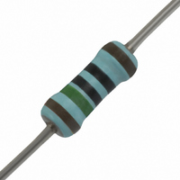
Manufacturer Part Number
SFR2500001500FR500
Description
RES 150 OHM METAL FILM .40W 1%
Manufacturer
Vishay
Series
SFR25r
Specifications of SFR2500001500FR500
Temperature Coefficient
±100ppm/°C
Resistance (ohms)
150
Power (watts)
0.4W
Composition
Metal Film
Tolerance
±1%
Size / Dimension
0.098" Dia x 0.295" L (2.50mm x 7.50mm)
Lead Style
Through Hole
Package / Case
Axial
Resistance In Ohms
150
Case
Axial
Resistance
150ohm
Resistance Tolerance
± 1%
Power Rating
400mW
Voltage Rating
250V
Resistor Element Material
Metal Film
Lead Free Status / RoHS Status
Lead free / RoHS Compliant
Features
-
Height
-
Lead Free Status / RoHS Status
Lead free / RoHS Compliant, Lead free / RoHS Compliant
Other names
5043ED150R0F12AF5
PPC150YTR
PPC150YTR


TESTS AND REQUIREMENTS
Essentially all tests are carried out in accordance with the schedule of
“IEC publication 60115-1”, category 55/155/56 (rated temperature range
the requirements specified by EIA and EIAJ.
The tests are carried out in accordance with IEC publication 60068-2,
“Recommended basic climatic and mechanical robustness testing
procedure for electronic components” and under standard atmospheric
conditions according to “IEC 60068-1”, subclause 5.3.
Table 7
4.16
4.16.2
4.16.3
4.16.4
4.17
4.18
4.19
4.20
4.22
55 C to +155 C; damp heat, long term, 56 days). The testing also covers
60115-1
CLAUSE
IEC
Test procedures and requirements
21 (U)
21 (Ua1)
21 (Ub)
21 (Uc)
20 (Ta)
20 (Tb)
14 (Na)
29 (Eb)
6 (Fc)
METHOD
60068-2
TEST
IEC
robustness of
terminations:
solderability
resistance to
soldering heat
rapid change of
temperature
bump
vibration
tensile all samples
bending half
number of
samples
torsion other half
of samples
TEST
3
thermal shock: 3 s; 350 C;
6 mm from body
30 minutes at 55 C and
30 minutes at +155 C; 5 cycles
3
40 g
frequency 10 to 500 Hz;
displacement 1.5 mm or
acceleration 10 g; 3 directions;
total 6 hours (3
2 s; 235 C; flux 600
0.45 mm, load 5 N; 10 s
0.58 mm, load 10 N; 10 s
0.45 mm, load 2.5 N; 4
0.58 mm, load 5 N; 4
360 in opposite directions
1500 bumps in 3 directions;
PROCEDURE
2 hours)
90
90
In Table 7 the tests and requirements are listed with reference to the relevant
clauses of “IEC publications 60115-1 and 60068-2”; a short description of
the test procedure is also given. In some instances deviations from the IEC
recommendations were necessary for our method of specifying.
RESISTANCE
RANGE
(5033E)
SFR16S
number of failures 10
number of failures 10
R/R max.: 0.25% + 0.05
R/R max.: 0.25% + 0.05
R/R max.: 0.25% + 0.05
R/R max.: 0.25% + 0.05
R/R max.: 0.25% + 0.05
good tinning; no damage
REQUIREMENTS
no damage
no damage
no damage
(5043E)
SFR25
10
10
(5053H)
SFR25H
6
6
Related parts for SFR2500001500FR500
Image
Part Number
Description
Manufacturer
Datasheet
Request
R

Part Number:
Description:
357-036-542-201 CARDEDGE 36POS DL .156 BLK LOPRO
Manufacturer:
Vishay
Datasheet:
Part Number:
Description:
357-036-542-201 CARDEDGE 36POS DL .156 BLK LOPRO
Manufacturer:
Vishay
Datasheet:
Part Number:
Description:
357-036-542-201 CARDEDGE 36POS DL .156 BLK LOPRO
Manufacturer:
Vishay
Datasheet:
Part Number:
Description:
357-036-542-201 CARDEDGE 36POS DL .156 BLK LOPRO
Manufacturer:
Vishay
Datasheet:
Part Number:
Description:
357-036-542-201 CARDEDGE 36POS DL .156 BLK LOPRO
Manufacturer:
Vishay
Datasheet:
Part Number:
Description:
357-036-542-201 CARDEDGE 36POS DL .156 BLK LOPRO
Manufacturer:
Vishay
Datasheet:
Part Number:
Description:
357-036-542-201 CARDEDGE 36POS DL .156 BLK LOPRO
Manufacturer:
Vishay
Datasheet:
Part Number:
Description:
357-036-542-201 CARDEDGE 36POS DL .156 BLK LOPRO
Manufacturer:
Vishay
Datasheet:
Part Number:
Description:
357-036-542-201 CARDEDGE 36POS DL .156 BLK LOPRO
Manufacturer:
Vishay
Datasheet:
Part Number:
Description:
357-036-542-201 CARDEDGE 36POS DL .156 BLK LOPRO
Manufacturer:
Vishay
Datasheet:
Part Number:
Description:
357-036-542-201 CARDEDGE 36POS DL .156 BLK LOPRO
Manufacturer:
Vishay
Datasheet:
Part Number:
Description:
357-036-542-201 CARDEDGE 36POS DL .156 BLK LOPRO
Manufacturer:
Vishay
Datasheet:
Part Number:
Description:
357-036-542-201 CARDEDGE 36POS DL .156 BLK LOPRO
Manufacturer:
Vishay
Datasheet:
Part Number:
Description:
357-036-542-201 CARDEDGE 36POS DL .156 BLK LOPRO
Manufacturer:
Vishay
Datasheet:
Part Number:
Description:
357-036-542-201 CARDEDGE 36POS DL .156 BLK LOPRO
Manufacturer:
Vishay
Datasheet: