NFR0300001008JAC00 Vishay, NFR0300001008JAC00 Datasheet
NFR0300001008JAC00
Specifications of NFR0300001008JAC00
230621013108
5093FM1R000J08AFX
PPC1.0ETB


Related parts for NFR0300001008JAC00

NFR0300001008JAC00 Summary of contents
Page 1
... Resistance to Soldering Heat Note Resistance values below 0.47 Ω with ± tolerance are available on request (1) Document Number: 30256 For technical questions, contact: filmresistors.leaded@vishay.com Revision: 06-Dec-07 FEATURES • Metal film technology • High power (upto small package • Small standard sizes (0207/0414/0617) • ...
Page 2
... Notes (1) The PART NUMBER is shown to facilitate the introduction of the unified part numbering system (2) Please refer to table PACKAGING, see next page www.vishay.com For technical questions, contact: filmresistors.leaded@vishay.com 2 Fusible Power Metal Film Leaded Resistors Last Digit of 12NC Indicating Resistance Decade RESISTANCE DECADE 0.47 Ω to 0.91 Ω ...
Page 3
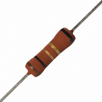
... There is a fifth black band in order to indicate the type of resistor. Standard values of nominal resistance are taken from the E24 series for resistors with a tolerance of ± FUNCTIONAL PERFORMANCE 100 Derating - Standard Operation Maximum dissipation (P Document Number: 30256 For technical questions, contact: filmresistors.leaded@vishay.com Revision: 06-Dec-07 Fusible Power Metal Film Leaded Resistors REEL CODE ...
Page 4
... P (W) Hot spot temperature rise (Δ function of dissipated power www.vishay.com For technical questions, contact: filmresistors.leaded@vishay.com 4 Fusible Power Metal Film Leaded Resistors Δ T (°C) 0.6 0.8 1.0 Temperature rise (ΔT) at the lead end (soldering point function of dissipated power at various leads Δ ...
Page 5
... TEST TEST CLAUSE METHOD Temperature 4.8 - coefficient 4.25.1 - Endurance at 70 °C 4.26 - Accidental overload Document Number: 30256 For technical questions, contact: filmresistors.leaded@vishay.com Revision: 06-Dec-07 Fusible Power Metal Film Leaded Resistors 100 80 60 Δ T (° 2.0 2.5 3.0 Temperature rise (ΔT) at the lead end (soldering ...
Page 6
... Component solvent 4.29 45 (XA) resistance Voltage proof on 4.7 - insulation 4.6.1.1 - Insulation resistance www.vishay.com For technical questions, contact: filmresistors.leaded@vishay.com 6 Fusible Power Metal Film Leaded Resistors PROCEDURE 56 days; 40 ° loaded with 0.01 Pn Load Load 90° 360° in opposite direction 30 min at LCT; 30 min at UCT; ...
Page 7
... Vishay product could result in personal injury or death. Customers using or selling Vishay products not expressly indicated for use in such applications their own risk and agree to fully indemnify and hold Vishay and its distributors harmless from and against any and all claims, liabilities, expenses and damages arising or resulting in connection with such use or sale, including attorneys fees, even if such claim alleges that Vishay or its distributor was negligent regarding the design or manufacture of the part ...