RTO020FR2000JTE3 Vishay, RTO020FR2000JTE3 Datasheet - Page 2
RTO020FR2000JTE3
Manufacturer Part Number
RTO020FR2000JTE3
Description
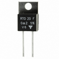
RES .20 OHM 20W 5% TO-220
Manufacturer
Vishay
Series
RTO 20r
Datasheet
1.RTO020F2R200JTE3.pdf
(4 pages)
Specifications of RTO020FR2000JTE3
Resistance
0.2 Ohms
Power Rating
20 Watts
Voltage Rating
250 Volts
Temperature Coefficient
±250ppm/°C
Resistance (ohms)
0.2
Power (watts)
20W
Composition
Thick Film
Features
Non-Inductive
Tolerance
±5%
Size / Dimension
0.398" L x 0.177" W (10.10mm x 4.50mm)
Height
0.591" (15.00mm)
Lead Style
Through Hole
Package / Case
TO-220-2
Resistance In Ohms
0.20
Case
TO-220
Termination Style
Radial
Operating Temperature Range
- 55 C to + 155 C
Dimensions
10.1 mm W x 15 mm L x 4.5 mm H
Lead Spacing
5.08 mm
Product
Thick Film Resistors Leaded
Resistance Tolerance
± 5%
Resistor Element Material
Thick Film
Lead Free Status / RoHS Status
Lead free / RoHS Compliant
Lead Free Status / RoHS Status
Lead free / RoHS Compliant, Lead free / RoHS Compliant
Other names
RT20J-.20


Note
• For very low ohmic values, TCR for information
CHOICE OF THE HEATSINK
The user must choose according to the working conditions of the component (power, room temperature).
Maximum working temperature must not exceed 155 °C. The dissipated power is simply calculated by the following ratio:
Example:
R
Thermal resistance R
Considering equation (1) we have:
Document Number: 50005
Revision: 18-May-09
TH (c - a)
PERFORMANCE
TESTS
Momentary Overload
Rapid Temperature Change
Load Life
Humidity (Steady State)
High Temperature Exposure
Vibration
Terminal Strength
Shock
RESISTANCE VALUE IN RELATION TO TOLERANCE AND TCR
Resistance Values
Tolerances
Typical Temperature
Coefficient Range
(- 55 °C to + 155 °C)
P:
ΔT:
R
R
ΔT
R
R
TH (j - c)
TH (c - a)
TH (j - c)
TH (c - a)
=
: For RTO 20 power rating 10 W at ambient temperature + 25 °C
155 °C - 25 °C
:
:
+ R
= 13 °C/W - 6.5 °C/W = 6.5 °C/W
TH (c - a)
Expressed in W
Difference between maximum working temperature and room temperature
Thermal resistance value measured between resistive layer and outer side of the resistor. It is the thermal
resistance of the component: (Special Features table)
Thermal resistance value measured between outer side of the resistor and room temperature. It is the thermal
resistance of the heatsink itself (type, shape) and the quality of the fastening device.
TH (j - c)
=
=
130 °C
ΔT
------- =
20 W Power Resistor, Thick Film Technology, TO-220
: 6.5 °C/W
P
± 900 ppm/°C
130
--------- - = 13 °C/W
10
≥ 0.01
For technical questions, contact:
MIL STD 202, Method 204 C Test D
MIL STD 202, Method 211 Test A1
P =
1000 h - 40 % P
EN 60115-1/60068-2-14
Saw tooth: 100 g/6 ms
1.6 P
1000 h P
---------------------------------------------------------- -
[
2 P
- 55 °C to + 155 °C
56 days R.H. 95 %
R
IEC 60068-2-27
NF EN 140 000
TH (j - c)
CONDITIONS
± 700 ppm/°C
IEC 60115-1
r
EN 60115-1
EN 60115-1
EN 60115-1
U
r
5 s for R < 2 Ω
S
5 s for R ≥ 2 Ω
5 cycles
≥ 0.015
< 1.5 U
r
at + 25 °C
ΔT
+ R
r
at + 100 °C
TH (c - a)
L
± 1 % at ± 10 %
sfer@vishay.com
]
1 ( )
± 250 ppm/°C
≥ 0.1
± (0.25 % + 0.005 Ω)
± (0.5 % + 0.005 Ω)
± (0.5 % + 0.005 Ω)
± (0.5 % + 0.005 Ω)
± (0.2 % + 0.005 Ω)
± (0.2 % + 0.005 Ω)
± (0.5 % + 0.005 Ω)
REQUIREMENTS
± (1 % + 0.005 Ω)
Vishay Sfernice
± 150 ppm/°C
≥ 0.5
www.vishay.com
RTO 20
35
Related parts for RTO020FR2000JTE3
Image
Part Number
Description
Manufacturer
Datasheet
Request
R

Part Number:
Description:
357-036-542-201 CARDEDGE 36POS DL .156 BLK LOPRO
Manufacturer:
Vishay
Datasheet:
Part Number:
Description:
357-036-542-201 CARDEDGE 36POS DL .156 BLK LOPRO
Manufacturer:
Vishay
Datasheet:
Part Number:
Description:
357-036-542-201 CARDEDGE 36POS DL .156 BLK LOPRO
Manufacturer:
Vishay
Datasheet:
Part Number:
Description:
357-036-542-201 CARDEDGE 36POS DL .156 BLK LOPRO
Manufacturer:
Vishay
Datasheet:
Part Number:
Description:
357-036-542-201 CARDEDGE 36POS DL .156 BLK LOPRO
Manufacturer:
Vishay
Datasheet:
Part Number:
Description:
357-036-542-201 CARDEDGE 36POS DL .156 BLK LOPRO
Manufacturer:
Vishay
Datasheet:
Part Number:
Description:
357-036-542-201 CARDEDGE 36POS DL .156 BLK LOPRO
Manufacturer:
Vishay
Datasheet:
Part Number:
Description:
357-036-542-201 CARDEDGE 36POS DL .156 BLK LOPRO
Manufacturer:
Vishay
Datasheet:
Part Number:
Description:
357-036-542-201 CARDEDGE 36POS DL .156 BLK LOPRO
Manufacturer:
Vishay
Datasheet:
Part Number:
Description:
357-036-542-201 CARDEDGE 36POS DL .156 BLK LOPRO
Manufacturer:
Vishay
Datasheet:
Part Number:
Description:
357-036-542-201 CARDEDGE 36POS DL .156 BLK LOPRO
Manufacturer:
Vishay
Datasheet:
Part Number:
Description:
357-036-542-201 CARDEDGE 36POS DL .156 BLK LOPRO
Manufacturer:
Vishay
Datasheet:
Part Number:
Description:
357-036-542-201 CARDEDGE 36POS DL .156 BLK LOPRO
Manufacturer:
Vishay
Datasheet:
Part Number:
Description:
357-036-542-201 CARDEDGE 36POS DL .156 BLK LOPRO
Manufacturer:
Vishay
Datasheet:
Part Number:
Description:
357-036-542-201 CARDEDGE 36POS DL .156 BLK LOPRO
Manufacturer:
Vishay
Datasheet: