VR37000001005JA100 Vishay, VR37000001005JA100 Datasheet - Page 4
VR37000001005JA100
Manufacturer Part Number
VR37000001005JA100
Description
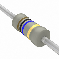
RES 1/2W HV 10M AXIAL AMMO PAK
Manufacturer
Vishay
Series
VR37r
Type
Metal Glazer
Datasheet
1.VR37000001005JA100.pdf
(6 pages)
Specifications of VR37000001005JA100
Resistance
10Mohm
Temperature Coefficient
±200ppm/°C
Resistance (ohms)
10M
Power (watts)
0.5W, 1/2W
Composition
Metal Film
Features
Pulse Withstanding
Tolerance
±5%
Size / Dimension
0.157" Dia x 0.394" L (4.00mm x 10.00mm)
Lead Style
Through Hole
Package / Case
Axial
Resistance In Ohms
10.0M
Case
Axial
Power Rating(s)
1/2W
Tolerance (+ Or -)
5%
Mounting Style
Through Hole
Construction
Axial
Operating Temp Range
-55C to 155C
Case Style
Conformal
Military Standard
Not Required
Failure Rate
Not Required
Lead Spacing (nom)
Not Requiredmm
Product Length (mm)
10mm
Product Depth (mm)
Not Requiredmm
Product Height (mm)
Not Requiredmm
Resistance Tolerance
± 5%
Power Rating
500mW
Voltage Rating
3.5kV
Resistor Element Material
Metal Film
Termination Style
Axial
Dimensions
4 mm Dia. x 9 mm L
Lead Free Status / RoHS Status
Lead free / RoHS Compliant
Height
-
Lead Free Status / Rohs Status
Details
Other names
5053DM10M00J08AFX
Q1390232
Q1390232
Available stocks
Company
Part Number
Manufacturer
Quantity
Price


Application Information
TESTS AND REQUIREMENTS
Essentially all tests are carried out in accordance with
IEC 60115-1 specification, category LCT/UCT/56 (rated
temperature range: Lower Category Temperature, Upper
Category Temperature; damp heat, long term, 56 days).
The tests are carried out in accordance with IEC 60068-2-xx.
Test method under standard atmospheric conditions
according to IEC 60068-1, 5.3.
Document Number: 28733
Revision: 12-Oct-09
Hot-spot temperature rise (ΔT) as a function of dissipated power
TEST PROCEDURES AND REQUIREMENTS
IEC
60115-1
CLAUSE
4.16
4.16.2
4.16.3
4.16.4
4.17
4.18
4.19
Δ T
(K)
80
60
40
20
0
0
METHOD
60068-2-
21 (Ua1)
21 (Ub)
14 (Na)
21 (Uc)
20 (Tb)
20 (Ta)
TEST
IEC
0.4
Rapid change of temperature
Robustness of terminations:
Bending half number
Tensile all samples
Torsion other half
soldering heat
Resistance to
Solderability
Solderability
(after aging)
For technical questions, contact:
of samples
of samples
TEST
0.8
Metal Glaze Leaded Resistors
P (W)
High Ohmic/High Voltage
1.2
2 s; 235 °C: Solder bath method; SnPb40
for 2 s at 235 °C; solder bath (SnPb40)
3 s; 245 °C: Solder bath method;
3 x 360° in opposite directions
Thermal shock: 10 s; 260 °C;
for 3 s at 245 °C; solder bath
30 min at + 155 °C; 5 cycles
Ø 0.7 mm; load 5 N; 4 x 90°
Ø 0.7 mm; load 10 N; 10 s
8 h steam or 16 h 155 °C;
filmresistorsleaded@vishay.com
leads immersed 6 mm;
(SnAg3Cu0.5) method
30 min at - 55 °C and
In the Test Procedures and Requirements table the tests
and requirements are listed with reference to the relevant
clauses of IEC 60115-1 and IEC 60068-2-xx test methods. A
short description of the test procedure is also given. In some
instances deviations from the IEC recommendations were
necessary for our method of specifying.
All soldering tests are performed with mildly activated flux.
3 mm from body
PROCEDURE
SnAg3Cu0.5
∆ T
(K)
50
40
30
20
10
0
point) as a function of dissipated power at various
Temperature rise (ΔT) at the lead end (soldering
0
lead lengths after mounting
0.4
Vishay BCcomponents
Good tinning (≥ 95 % covered); no
Good tinning (≥ 95 % covered); no
ΔR max.: ± (0.5 % R + 0.05 Ω)
ΔR max.: ± (0.5 % R + 0.05 Ω)
ΔR max.: ± (0.5 % R + 0.05 Ω)
Number of failures < 10 x 10
Number of failures < 10 x 10
5 mm
10 mm
15 mm
REQUIREMENTS
No damage
0.8
damage
damage
P (W)
www.vishay.com
VR37
1.2
-6
-6
205
Related parts for VR37000001005JA100
Image
Part Number
Description
Manufacturer
Datasheet
Request
R

Part Number:
Description:
357-036-542-201 CARDEDGE 36POS DL .156 BLK LOPRO
Manufacturer:
Vishay
Datasheet:
Part Number:
Description:
357-036-542-201 CARDEDGE 36POS DL .156 BLK LOPRO
Manufacturer:
Vishay
Datasheet:
Part Number:
Description:
357-036-542-201 CARDEDGE 36POS DL .156 BLK LOPRO
Manufacturer:
Vishay
Datasheet:
Part Number:
Description:
357-036-542-201 CARDEDGE 36POS DL .156 BLK LOPRO
Manufacturer:
Vishay
Datasheet:
Part Number:
Description:
357-036-542-201 CARDEDGE 36POS DL .156 BLK LOPRO
Manufacturer:
Vishay
Datasheet:
Part Number:
Description:
357-036-542-201 CARDEDGE 36POS DL .156 BLK LOPRO
Manufacturer:
Vishay
Datasheet:
Part Number:
Description:
357-036-542-201 CARDEDGE 36POS DL .156 BLK LOPRO
Manufacturer:
Vishay
Datasheet:
Part Number:
Description:
357-036-542-201 CARDEDGE 36POS DL .156 BLK LOPRO
Manufacturer:
Vishay
Datasheet:
Part Number:
Description:
357-036-542-201 CARDEDGE 36POS DL .156 BLK LOPRO
Manufacturer:
Vishay
Datasheet:
Part Number:
Description:
357-036-542-201 CARDEDGE 36POS DL .156 BLK LOPRO
Manufacturer:
Vishay
Datasheet:
Part Number:
Description:
357-036-542-201 CARDEDGE 36POS DL .156 BLK LOPRO
Manufacturer:
Vishay
Datasheet:
Part Number:
Description:
357-036-542-201 CARDEDGE 36POS DL .156 BLK LOPRO
Manufacturer:
Vishay
Datasheet:
Part Number:
Description:
357-036-542-201 CARDEDGE 36POS DL .156 BLK LOPRO
Manufacturer:
Vishay
Datasheet:
Part Number:
Description:
357-036-542-201 CARDEDGE 36POS DL .156 BLK LOPRO
Manufacturer:
Vishay
Datasheet:
Part Number:
Description:
357-036-542-201 CARDEDGE 36POS DL .156 BLK LOPRO
Manufacturer:
Vishay
Datasheet: