FX2C-52S-1.27DSA(71) Hirose Electric Co Ltd, FX2C-52S-1.27DSA(71) Datasheet - Page 23
FX2C-52S-1.27DSA(71)
Manufacturer Part Number
FX2C-52S-1.27DSA(71)
Description
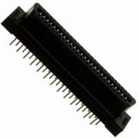
CONN RECEPT VERT 52POS 1.27MM
Manufacturer
Hirose Electric Co Ltd
Series
FX2r
Datasheet
1.FX2CA-20P-1.27DSA71.pdf
(28 pages)
Specifications of FX2C-52S-1.27DSA(71)
Connector Type
Receptacle, Outer Shroud Contacts
Number Of Positions
52
Pitch
0.050" (1.27mm)
Number Of Rows
2
Mounting Type
Through Hole
Contact Finish
Gold
Mated Stacking Heights
12mm, 12.1mm, 13mm, 14mm
Height Above Board
0.374" (9.50mm)
Product Type
Receptacles
Lead Free Status / RoHS Status
Lead free / RoHS Compliant
Features
-
Contact Finish Thickness
-
Lead Free Status / Rohs Status
Lead free / RoHS Compliant
Other names
*FX2C-52S-1.27DSA(71)
H10595
H10595


The product information in this catalog is for reference only. Please request the Engineering Drawing for the most current and accurate design information.
All non-RoHS products have been discontinued, or will be discontinued soon. Please check the products status on the Hirose website RoHS search at www.hirose-connectors.com, or contact your Hirose sales representative.
■Header SMT Type
●Straight Type
BPCB mounting pattern
FX2-100P-1.27SVL(71)
FX2-120P-1.27SV(71)
FX2-120P-1.27SVL(71)
FX2-020P-1.27SV(71)
FX2-020P-1.27SVL(71)
FX2-032P-1.27SV(71)
FX2-032P-1.27SVL(71)
FX2-040P-1.27SV(71)
FX2-040P-1.27SVL(71)
FX2-052P-1.27SV(71)
FX2-052P-1.27SVL(71)
FX2-060P-1.27SV(71)
FX2-060P-1.27SVL(71)
FX2-068P-1.27SV(71)
FX2-068P-1.27SVL(71)
FX2-080P-1.27SV(71)
FX2-080P-1.27SVL(71)
FX2-100P-1.27SV(71)
Part Number
572-2001-9-71
572-2051-7-71
572-2002-1-71
572-2052-0-71
572-2003-4-71
572-2053-2-71
572-2004-7-71
572-2054-5-71
572-2005-0-71
572-2055-8-71
572-2006-2-71
572-2056-0-71
572-2007-5-71
572-2057-3-71
572-2008-8-71
572-2058-6-71
572-2009-0-71
572-2059-9-71
CL No.
Number of Contacts
100
120
20
32
40
52
60
68
80
22.75
30.37
35.45
43.07
48.15
53.23
60.85
73.55
86.25
A
FX2 Series●1.27mm Pitch Multi-function Two Piece Connector
Note : The connector positioning bosses are constructed to press fit
into the board with light force. When mounting on the board,
press the connector lightly from the top and check that the
positioning bosses are securely inserted in the board holes
and that the connector leads are engaged in the board.
The recommended boss hole for use with automatic mounting is
illustrated in fig. 1.
11.43
19.05
24.13
31.75
36.83
41.91
49.53
62.23
74.93
B
16.51
24.13
29.21
36.83
41.91
46.99
54.61
67.31
80.01
C
25.75
33.37
38.45
46.07
51.15
56.23
63.85
76.55
89.25
_ _ _ _ _ _ _ _
_ _ _ _ _ _ _ _
_ _ _ _ _ _ _ _
_ _ _ _ _ _ _ _
_ _ _ _ _ _ _ _
_ _ _ _ _ _ _ _
_ _ _ _ _ _ _ _
_ _ _ _ _ _ _ _
_ _ _ _ _ _ _ _
D
21.15
28.77
33.85
41.47
46.55
51.63
59.25
71.95
84.65
_ _ _ _ _ _ _ _
_ _ _ _ _ _ _ _
_ _ _ _ _ _ _ _
_ _ _ _ _ _ _ _
_ _ _ _ _ _ _ _
_ _ _ _ _ _ _ _
_ _ _ _ _ _ _ _
_ _ _ _ _ _ _ _
_ _ _ _ _ _ _ _
E
FIG.1
Unit: mm
1.75±0.05
RoHS
YES
A107
Related parts for FX2C-52S-1.27DSA(71)
Image
Part Number
Description
Manufacturer
Datasheet
Request
R

Part Number:
Description:
CONN RECEPT VERT 52POS 1.27MM
Manufacturer:
Hirose Electric Co Ltd
Datasheet:
Part Number:
Description:
Conn Rectangular PL 14 POS 2.54mm Crimp RA Cable Mount
Manufacturer:
Hirose Electric Co Ltd
Part Number:
Description:
Conn Shrouded Header HDR 10 POS 2mm Solder ST SMD Embossed T/R
Manufacturer:
Hirose Electric Co Ltd
Datasheet:
Part Number:
Description:
DF11-20DP-2DSA(24)
Manufacturer:
Hirose Electric Co Ltd
Datasheet:
Part Number:
Description:
CONN HEADER 60POS 1.27MM R/A AU
Manufacturer:
Hirose Electric Co Ltd
Datasheet:
Part Number:
Description:
CONN HEADER STR 32POS 1.27MM SMD
Manufacturer:
Hirose Electric Co Ltd
Datasheet:
Part Number:
Description:
CONN RECEPT STR 32POS 1.27MM SMD
Manufacturer:
Hirose Electric Co Ltd
Datasheet:
Part Number:
Description:
Conn Shrouded Header HDR 6 POS 2mm Solder ST Thru-Hole Bag
Manufacturer:
Hirose Electric Co Ltd
Datasheet:
Part Number:
Description:
Conn Shrouded Header HDR 8 POS 2mm Solder ST Thru-Hole Tube
Manufacturer:
Hirose Electric Co Ltd
Datasheet:
Part Number:
Description:
Conn Shrouded Header HDR 26 POS 2mm Solder ST SMD
Manufacturer:
Hirose Electric Co Ltd
Datasheet:
Part Number:
Description:
Conn Shrouded Header HDR 22 POS 2mm Solder ST SMD
Manufacturer:
Hirose Electric Co Ltd
Part Number:
Description:
Conn Shrouded Header HDR 22 POS 2mm Solder ST SMD
Manufacturer:
Hirose Electric Co Ltd
Part Number:
Description:
2mm 22w Wire to Board IDC Crimp Connector
Manufacturer:
Hirose Electric Co Ltd
Part Number:
Description:
Conn Board to Board HDR 40 POS 0.5mm Solder ST SMD Embossed T/R
Manufacturer:
Hirose Electric Co Ltd
Datasheet: