MAL212016222E3 Vishay, MAL212016222E3 Datasheet - Page 5
MAL212016222E3
Manufacturer Part Number
MAL212016222E3
Description
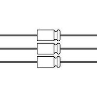
CAP 2200UF 25V ELECT AXIAL
Manufacturer
Vishay
Series
120 ATCr
Datasheet
1.MAL212025681E3.pdf
(8 pages)
Specifications of MAL212016222E3
Capacitance
2200µF
Voltage Rating
25V
Tolerance
±20%
Lifetime @ Temp.
8000 Hrs @ 125°C
Operating Temperature
-40°C ~ 125°C
Features
Automotive
Ripple Current
3.31A
Esr (equivalent Series Resistance)
43.0 mOhm
Impedance
44 mOhm
Mounting Type
Through Hole
Package / Case
Axial, Can
Size / Dimension
0.709" Dia x 1.181" L (18.00mm x 30.00mm)
Operating Temperature Range
- 40 C to + 125 C
Termination Style
Axial
Dimensions
0.73 in Dia. x 1.2 in L
Product
High Temp Electrolytic Capacitors
Lead Free Status / RoHS Status
Lead free / RoHS Compliant
Height
-
Lead Spacing
-
Surface Mount Land Size
-
Lead Free Status / Rohs Status
Details
Other names
4528PHBK


CAPACITANCE (C)
Document Number: 28336
Revision: 02-Sep-10
ADDITIONAL ELECTRICAL DATA
Voltage
Surge voltage
Reverse voltage
Current
Leakage current
Inductance
Equivalent series inductance (ESL)
C
All voltages; all case sizes
C
63 V types
ESR
ESR
C
ESR
0
0
1.1
1.0
0.9
0.8
1.2
10
10
1
= capacitance at 20 °C, 100 Hz
- 40
-1
- 40
0
0
= typical at 20 °C
Curve 1: All case sizes; 100 Hz
Curve 2: Case Ø D x L = 18 x 38 and 21 x 38 mm; 10 to 100 kHz
Curve 3: Case Ø D x L = 15 x 30 and 18 x 30 mm; 10 to 100 kHz
Curve 4: Case Ø D x L = 10 x 30 and 12.5 x 30 mm; 10 to 100 kHz
Fig.7 Typical multiplier of ESR as a function of ambient
Fig.5 Typical multiplier of capacitance as a function
- 20
- 20
PARAMETER
0
0
temperature at different frequencies
- 20
- 20
of ambient temperature
- 40
- 40
- 60
Axial High Temperature, High Ripple Current
- 60
- 80 - 100
- 80 - 100 - 120 - 140 - 160
For technical questions, contact:
After 1 min at U
After 5 min at U
CaseØ D x L mm:
- 120
Aluminum Capacitors
T
T
CONDITIONS
amb
amb
- 140
12.5 x 30
10 x 30
15 x 30
18 x 30
18 x 38
21 x 38
(°C)
(°C)
R
R
- 160
1
2
3
4
EQUIVALENT SERIES RESISTANCE (ESR)
ESR
≤ 40 V types
ESR
ESR
100 V types
ESR
ESR
ESR
10
10
10
1
10
10
1
- 40
- 40
-1
aluminumcaps1@vishay.com
0
0
0
0
-1
2
= typical at 20 °C
= typical at 20 °C
Curve 1: All case sizes; 100 Hz
Curve 2: Case Ø D x L = 18 x 38 and 21 x 38 mm; 10 to 100 kHz
Curve 3: Case Ø D x L = 10 x 30 and 18 x 30 mm; 10 to 100 kHz
Curve 1: All case sizes; 100 Hz
Curve 2: Case Ø D x L = 18 x 38 and 21 x 38 mm; 10 to 100 kHz
Curve 3: Case Ø D x L = 15 x 30 and 18 x 30 mm; 10 to 100 kHz
Curve 4: Case Ø D x L = 10 x 30 and 12.5 x 30 mm; 10 to 100 kHz
Fig.6 Typical multiplier of ESR as a function of ambient
Fig.8 Typical multiplier of ESR as a function of ambient
U
U
I
I
L
L
- 20
- 20
typ. 38 nH
typ. 46 nH
typ. 48 nH
typ. 50 nH
typ. 54 nH
typ. 59 nH
s
rev
1 0.012 C
5 0.004 C
1.15 x U
1 V
0
0
temperature at different frequencies
temperature at different frequencies
AXIAL
- 20
- 20
R
R
R
x U
x U
- 40
- 40
R
R
+ 40 µA
+ 40 µA
Vishay BCcomponents
- 60
- 60
VALUE
- 80 - 100
- 80 - 100
typ. 39 nH
typ. 39 nH
typ. 39 nH
typ. 39 nH
MOUNTING RING
- 120
- 120
120 ATC
www.vishay.com
T
T
amb
amb
- 140
- 140
(°C)
(°C)
- 160
- 160
1
2
3
4
1
2
3
5
Related parts for MAL212016222E3
Image
Part Number
Description
Manufacturer
Datasheet
Request
R

Part Number:
Description:
357-036-542-201 CARDEDGE 36POS DL .156 BLK LOPRO
Manufacturer:
Vishay
Datasheet:
Part Number:
Description:
357-036-542-201 CARDEDGE 36POS DL .156 BLK LOPRO
Manufacturer:
Vishay
Datasheet:
Part Number:
Description:
357-036-542-201 CARDEDGE 36POS DL .156 BLK LOPRO
Manufacturer:
Vishay
Datasheet:
Part Number:
Description:
357-036-542-201 CARDEDGE 36POS DL .156 BLK LOPRO
Manufacturer:
Vishay
Datasheet:
Part Number:
Description:
357-036-542-201 CARDEDGE 36POS DL .156 BLK LOPRO
Manufacturer:
Vishay
Datasheet:
Part Number:
Description:
357-036-542-201 CARDEDGE 36POS DL .156 BLK LOPRO
Manufacturer:
Vishay
Datasheet:
Part Number:
Description:
357-036-542-201 CARDEDGE 36POS DL .156 BLK LOPRO
Manufacturer:
Vishay
Datasheet:
Part Number:
Description:
357-036-542-201 CARDEDGE 36POS DL .156 BLK LOPRO
Manufacturer:
Vishay
Datasheet:
Part Number:
Description:
357-036-542-201 CARDEDGE 36POS DL .156 BLK LOPRO
Manufacturer:
Vishay
Datasheet:
Part Number:
Description:
357-036-542-201 CARDEDGE 36POS DL .156 BLK LOPRO
Manufacturer:
Vishay
Datasheet:
Part Number:
Description:
357-036-542-201 CARDEDGE 36POS DL .156 BLK LOPRO
Manufacturer:
Vishay
Datasheet:
Part Number:
Description:
357-036-542-201 CARDEDGE 36POS DL .156 BLK LOPRO
Manufacturer:
Vishay
Datasheet:
Part Number:
Description:
357-036-542-201 CARDEDGE 36POS DL .156 BLK LOPRO
Manufacturer:
Vishay
Datasheet:
Part Number:
Description:
357-036-542-201 CARDEDGE 36POS DL .156 BLK LOPRO
Manufacturer:
Vishay
Datasheet:
Part Number:
Description:
357-036-542-201 CARDEDGE 36POS DL .156 BLK LOPRO
Manufacturer:
Vishay
Datasheet: