ECJ-2FB1H823K Panasonic - ECG, ECJ-2FB1H823K Datasheet - Page 5
ECJ-2FB1H823K
Manufacturer Part Number
ECJ-2FB1H823K
Description
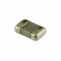
CAP .082UF 50V CERAMIC X7R 0805
Manufacturer
Panasonic - ECG
Series
ECJr
Datasheets
1.ECJ-RVB1H332M.pdf
(6 pages)
2.ECJ-RVB1H332M.pdf
(2 pages)
3.ECJ-RVB1H332M.pdf
(1 pages)
4.ECJ-RVB1H332M.pdf
(3 pages)
5.ECJ-0EB1H102K.pdf
(12 pages)
Specifications of ECJ-2FB1H823K
Capacitance
0.082µF
Voltage - Rated
50V
Tolerance
±10%
Temperature Coefficient
X7R
Mounting Type
Surface Mount, MLCC
Operating Temperature
-55°C ~ 125°C
Features
Low ESR
Applications
General Purpose
Package / Case
0805 (2012 Metric)
Size / Dimension
0.079" L x 0.049" W (2.00mm x 1.25mm)
Thickness
1.25mm
Lead Free Status / RoHS Status
Lead free / RoHS Compliant
Ratings
-
Lead Spacing
-
Other names
ECJ-2FB1H823K
ECJ2FB1H823K
ECJ2FB1H823K
PCC2451TR
Q1989096D
ECJ2FB1H823K
ECJ2FB1H823K
PCC2451TR
Q1989096D


Design and specifi cations are each subject to change without notice. Ask factory for the current technical specifi cations before purchase and/or use.
Should a safety concern arise regarding this product, please be sure to contact us immediately.
5.3 Hand Soldering
0201 to 1206, 0508, 0612, 0504
The rapid cooling (forced cooling) during Gradual
cooling part should be avoided, because this may
cause defects such as the thermal cracks, etc.
When the Capacitors are immersed into a cleaning
solvent, confi rm that the surface temperatures of the
devices do not exceed 100 °C.
Performing refl ow soldering twice under the conditions
shown in the fi gure above [Recommended profi le of
Refl ow soldering (EX)] will not cause any problems.
However, pay attention to the possible warp and
bending of the PC board.
Hand soldering typically causes signifi cant temperature
change, which may induce excessive thermal stresses
inside the Capacitors, resulting in the thermal cracks, etc.
In order to prevent any defects, the following should be
observed.
(1) Condition 1 (with preheating)
260
220
180
140
0201 to 1206, 0508, 0612, 0504
· The temperature of the soldering tips should be
· The direct contact of soldering tips with the Capacitors
· Dismounted Capacitors shall not be reused.
Recommended profi le of Refl ow soldering [Ex.]
Preheating
controlled with special care.
and/or terminal electrodes should be avoided.
Recommended profi le of Hand Soldering [Ex.]
(a) Soldering:
(b) Preheating:
(c) Temperature of Iron tip: 300 °C max.
(d) Gradual Cooling:
<Allowable temperature difference
<Allowable temperature difference
φ1.0 mm or below Thread eutectic solder with
soldering fl ux
✽
The Capacitors shall be preheated so that the
“Temperature Gradient” between the devices and
the tip of soldering iron is 150 °C or below.
(The required amount of solder shall be melted in
advance on the soldering tip.)
After soldering, the Capacitors shall be cooled
gradually at room temperature.
Rosin-based and non-activated fl ux is recommended.
60 to 120 sec
1210
Size
1210
Size
60 to 120 sec
✽
in the core.
1
Preheating
2
3 sec max.
Temp. rise
60 sec max.
3
4
Heating
Peak
Gradual cooling
Temp. Tol.
T < 150 °C
T < 130 °C
Temp. Tol
T < 150 °C
T < 130 °C
T>
T>
5
Gradual
cooling
Time
– EC52 –
Temperature of Iron tip
7. Inspection Process
6. Post Soldering Cleaning
Soldering time with a
6.3 Contamination of Cleaning Solvent
6.1 Cleaning Solvent
6.2 Cleaning Conditions
<Conditions of Hand soldering without preheating>
Shape of Iron tip
(2) Condition 2 (without preheating)
(1) Mounted PC boards shall be supported by an
(1) Insuffi cient cleaning can lead to:
(2) Excessive cleaning can lead to:
Cleaning with contaminated cleaning solvent may
cause the same results as insuffi cient cleaning due to
the high density of liberated halogen.
When mounted PC boards are inspected with measur-
ing terminal pins, abnormal and excess mechanical
stress shall not be applied to the PC board or mount-
ed components, to prevent failure or damage to the de-
vices.
S o ldering flu x residue may re main o n the P C
board if cleaned with an inappropriate solvent. This
may deteriorate the electrical characteristics and
reliability of the Capacitors.
Insuffi cient cleaning or excessive cleaning may impair the
electrical characteristics and reliability of the Capacitors.
soldering iron
Wattage
Hand soldering can be performed without preheating,
by following the conditions below:
(a) Soldering iron tip shall never directly touch
(b) The lands are suffi ciently preheated with a
adequate number of supporting pins with bend
settings of 90 mm span 0.5 mm max.
(a) The halogen substance found in the residue of
(b) The halogen substance found in the residue of
(c) Water-soluble soldering fl ux may have more
(a) Overuse of ultrasonic cleaning may deteriorate
Please follow these conditions for Ultrasonic cleaning:
Item
Size
the ceramic and terminal electrodes of the
Capacitors.
soldering iron tip before sliding the soldering
iron tip to the terminal electrodes of the
Capacitor for soldering.
soldering fl ux may cause the metal of terminal
electrodes to corrode.
soldering fl ux on the surface of the Capacitors
may change resistance values.
remarkable tendencies of (a) and (b) above
compared to those of rosin soldering fl ux.
the strength of the terminal electrodes or cause
cracking in the solder and /or ceramic bod-
ies of the Capacitors due to vibration of the PC
boards.
Ultrasonic wave output
Ultrasonic wave frequency
Ultrasonic wave cleaning time : 5 min max.
Multilayer Ceramic Capacitors
0201 to 0805, 0508, 0504
270 °C max.
φ3 mm max.
3 sec max.
20 W max.
Condition
: 20 W/L max.
: 40 kHz max.
1206, 1210, 0612
250 °C max.
00 Sep. 2008
Related parts for ECJ-2FB1H823K
Image
Part Number
Description
Manufacturer
Datasheet
Request
R

Part Number:
Description:
CAP ARRAY 22PF 50V NP0 0504
Manufacturer:
Panasonic - ECG
Datasheet:
Part Number:
Description:
CAP ARRAY 10PF 50V NP0 0504
Manufacturer:
Panasonic - ECG
Datasheet:
Part Number:
Description:
CAP ARRAY 100PF 50V NP0 0504
Manufacturer:
Panasonic - ECG
Datasheet:
Part Number:
Description:
CAP ARRAY 47PF 50V NP0 0504
Manufacturer:
Panasonic - ECG
Datasheet:
Part Number:
Description:
CAP ARRAY 2.2UF 6.3V X5R 0504
Manufacturer:
Panasonic - ECG
Datasheet:
Part Number:
Description:
CAP ARRAY .1UF 10V X5R 0504
Manufacturer:
Panasonic - ECG
Datasheet:
Part Number:
Description:
CAP ARRAY 1UF 6.3V X5R 0504
Manufacturer:
Panasonic - ECG
Datasheet:
Part Number:
Description:
CAP ARRAY 1UF 6.3V X5R 0504
Manufacturer:
Panasonic - ECG
Datasheet:
Part Number:
Description:
CAP ARRAY 1UF 10V X5R 0504
Manufacturer:
Panasonic - ECG
Datasheet:
Part Number:
Description:
CAP ARRAY 1UF 10V X5R 0504
Manufacturer:
Panasonic - ECG
Datasheet:


Part Number:
Description:
MICROPHONE OMNI 6X2.2MM W/CAP
Manufacturer:
Panasonic - ECG
Datasheet:

Part Number:
Description:
CAP .01UF 100V PEN FILM 1210 5%
Manufacturer:
Panasonic - ECG
Datasheet:

Part Number:
Description:
FILTER LINE 23.3MH 2A
Manufacturer:
Panasonic - ECG
Datasheet:

Part Number:
Description:
SAW FILTER PCS 1960 MHZ 50/150
Manufacturer:
Panasonic - ECG
Datasheet: