UPG2214TB-EVAL CEL, UPG2214TB-EVAL Datasheet
UPG2214TB-EVAL
Specifications of UPG2214TB-EVAL


Related parts for UPG2214TB-EVAL


UPG2214TB-EVAL Summary of contents
Page 1
... NEC's ½W LOW VOLTAGE L, S-BAND SPDT SWITCH DESCRIPTION NEC's UPG2214TB is a GaAs MMIC L, S-band SPDT (Single Pole Double Throw) switch for mobile phones and other L, S-band applications from 0.05 to 3.0 GHz. This device can operate from 1.8 to 5.3 V with low insertion = 3 ...
Page 2
PIN CONNECTIONS AND INTERNAL BLOCK DIAGRAM (Top View) (Top View TRUTH TABLE V V cont1 cont2 Low High High Low ABSOLUTE MAXIMUM RATINGS PARAMETER Switch Control Voltage Input Power Operating Ambient ...
Page 3
ELECTRICAL CHARACTERISTICS (T = +25° 3. blocking capacitors value = 100 pF, unless otherwise specified) A cont (H) cont (L) PARAMETER Insertion Loss 1 Insertion Loss 2 Insertion Loss 3 Insertion Loss 4 ...
Page 4
ELECTRICAL CHARACTERISTICS (T = +25° 1. blocking capacitors value = 100 pF, unless otherwise specified) A cont (H) cont (L) PARAMETER Insertion Loss 6 Insertion Loss 7 Insertion Loss 8 Insertion Loss 9 ...
Page 5
EVALUATION CIRCUIT 1,000 pF Note C0 : 0.05 to 0.5 GHz 1,000 pF : 0.5 to 3.0 GHz 100 pF The application circuits and their parameters are for reference only and are not intended for actual design-ins. OUTPUT1 OUTPUT2 C0 ...
Page 6
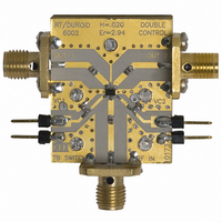
ILLUSTRATION OF THE TEST CIRCUIT ASSEMBLED ON EVALUATION BOARD V cont2 Vc2 INPUT IN Vc1 V cont1 USING THE NEC EVALUATION BOARD SYMBOL VALUES C1, C2, C3 100 pF C4, C5 1,000 pF 6pin SMM SPDT ...
Page 7
TYPICAL CHARACTERISTICS (T = +25° 3 cont (H) cont (L) INPUT-OUTPUT1 INSERTION LOSS vs. FREQUENCY 0.5 1.0 1.5 2.0 Frequency f ...
Page 8
INPUT-OUTPUT1 ISOLATION vs. FREQUENCY -10 - -40 -50 0.5 1.0 1.5 2.0 Frequency f (GHz) INPUT-OUTPUT1 INPUT RETURN LOSS vs. FREQUENCY -10 -20 1 ...
Page 9
OUTPUT POWER vs. INPUT POWER GHz Input Power P in Remark The graphs indicate nominal characteristics (dBm) ...
Page 10
PACKAGE DIMENSIONS 6-PIN SUPER MINIMOLD (UNIT: mm) 2.1±0.1 1.25±0.1 0.1 MIN. ...
Page 11
... These NEC products are not intended for use in life support devices, appliances, or systems where the malfunction of these products can reasonably be expected to result in personal injury. The customers of CEL using or selling these products for use in such applications their own risk and agree to fully indemnify CEL for all damages resulting from such improper use or sale. ...
Page 12
... CAS numbers and other limited information may not be available for release event shall CEL’s liability arising out of such information exceed the total purchase price of the CEL part(s) at issue sold by CEL to customer on an annual basis. ...