MGA-545P8-TR1 Avago Technologies US Inc., MGA-545P8-TR1 Datasheet
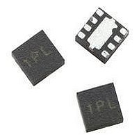
IC AMP RFIC GAAS 5.8GHZ 8-LPCC

MGA-545P8-TR1

Manufacturer Part Number
MGA-545P8-TR1
Description
IC AMP RFIC GAAS 5.8GHZ 8-LPCC
Manufacturer
Avago Technologies US Inc.
Datasheet

Specifications of MGA-545P8-TR1

Gain
11.5dB
Rf Type
WLL, WLAN
Current - Supply
135mA
Frequency
50MHz ~ 7GHz
Noise Figure
2.9dB
P1db
21.3dBm
Package / Case
8-LPCC
Test Frequency
3GHz
Voltage - Supply
3.3V
Frequency Range
50MHz To 7GHz
Noise Figure Typ
34dB
Power Dissipation Pd
800mW
Supply Current
135mA
Supply Voltage Range
3.3V
Lead Free Status / RoHS Status
Lead free / RoHS Compliant

Available stocks

Company
Part Number
Manufacturer
Quantity
Price
Part Number:
MGA-545P8-TR1
Manufacturer:
AVAGO
Quantity:
3 000
Part Number:
MGA-545P8-TR1
Manufacturer:
AVAGO/安华高
Quantity:
20 000
Part Number:
MGA-545P8-TR1G
Manufacturer:
AVAGO
Quantity:
10 000
MGA-545P8
50 MHz to 7 GHz Medium Power Amplifier
Data Sheet
Description
Avago’s MGA-545P8 is an economical, low current,
medium power, easy-to-use GaAs MMIC amplifier that
offers excellent power output at 5.8 GHz. Although
optimized for 5.8 GHz applications, the MGA-545P8 is
suitable for other applications in the 50 MHz to 7 GHz
frequency range.
With the addition of a simple input match, the MGA-
545P8 offers a small signal gain of 11.5 dB, a saturated
power output of 22 dBm and a saturated gain of 9.5 dB
at 5.8 GHz. The MGA-545P8 has a nominal current
consumption of 92 mA in saturated mode and 135 mA
in linear mode at a device voltage of 3.3 V with power
added efficiency of 46% in saturated mode.
The MGA-545P8 is housed in the 2X2 mm-8L LPCC
package. This package offers good thermal dissipation
and very good high frequency characteristics making
it appropriate for medium power applications through
7 GHz.
Pin Connections and Package Marking
Note: Package marking provides orientation and
“4T”= Device Code
“x” = Date code indicates the month of manufacture.
PIN 7 (OUT)
PIN 1
PIN 3
PIN 4
identification.
PIN 8
PIN 6
PIN 5
IN
BOTTOM VIEW
TOP VIEW
4Tx
Attention: Observe precautions for handling electrostatic sensitive devices.
Refer to Avago Application Note A004R: Electrostatic Discharge, Damage and Control.
PIN 8
OUT
PIN 6
PIN 5
PIN 1
PIN 2 (IN)
PIN 3
PIN 4
ESD Machine Model (Class A), ESD Human Body Model (Class 1A)
Simplified Schematic
INPUT
RF GND
BIAS
FET
Specifications
• 3.3 V, 92 mA, 5.825 GHz at saturation mode
• 22 dBm saturated power across1-7 GHz
• 9.5 dB gain
• 46% PAE
• 3.3 V, 135 mA, 5.825 GHz at linear mode
• 11.5 dB small signal gain
• Pout = 16 dBm at 5.6% EVM
• 34 dBm OIP3 at 2.7 V
Features
• Unconditionally stable
• Single +3.3 V operation
• Small package size: 2.0 x 2.0 x 0.75 mm
• Point MTTF > 300 years
• MSL-1 and Pb-free and Halogen-free
• Tape-and-reel packaging option available
Applications
The MGA-545P8 is ideal for use as IF Amplifier, driver
amplifier and power amplifier in:
• 3-4 GHz fixed wireless access (WLL)
• 5-6 GHz fixed wireless access (HiperLAN/UNII)
• 5-6 GHz WLAN 802.11a NIC and AP
• Other applications in the 50 MHz to 7 GHz frequency
range
OUTPUT
& V
d
Notes:
1. Enhancement mode technology em-
2. Refer to reliability datasheet for de-
3. Conform to JEDEC reference outline
[2]
ploys a single positive V
the need of negative gate voltage
associated with conventional depletion
mode devices.
tailed MTTF data.
MO229 for DRP-N.
3
gs
, eliminating

Related parts for MGA-545P8-TR1

MGA-545P8-TR1 Summary of contents

Page 1

... Point MTTF > 300 years • MSL-1 and Pb-free and Halogen-free • Tape-and-reel packaging option available Applications The MGA-545P8 is ideal for use as IF Amplifier, driver amplifier and power amplifier in: • 3-4 GHz fixed wireless access (WLL) • 5-6 GHz fixed wireless access (HiperLAN/UNII) • ...

Page 2

... MGA-545P8 Absolute Maximum Ratings Parameter V Device Voltage, RF output to ground Input Power in [2] Thermal Resistance jc [3] Pdiss Total Power Dissipation Tj Junction Temperature T Storage Temperature STG INPUT 4Tx Figure 1. Production test circuit. This circuit represents a match for maximum gain and saturated power. 0.01 µF ...

Page 3

... MGA-545P8 Electrical Specifications T = 25˚ 3.3 V, unless otherwise noted c d Symbol Parameter and Test Condition Gtest_sat Gain in test circuit at saturation For all frequencies refer to note [3] unless noted otherwise Gtest_ss Gain in test circuit at small signal For all frequencies refer to note [3] unless noted otherwise Psat Pout at 2 ...

Page 4

... MGA-545P8 Typical Performance 2 3 FREQUENCY (GHz) Figure 3. Small signal gain vs. frequency and [1,5] voltage . 2 3 FREQUENCY (GHz) Figure 6. Saturated power vs. frequency and [2,3,5] voltage . 2 3 FREQUENCY (GHz) Figure 9. Power added efficiency vs. ...

Page 5

V 95 3 (dBm) in Figure 12. Device current vs. P and in [4,5] voltage . 12 ...

Page 6

... MGA-545P8 Typical Scattering Parameters 3 Freq. S11 GHz Mag Ang dB 0.05 0.08 -144.5 24.4 0.1 0.11 -140.5 24.3 0.2 0.17 -132.4 24.0 0.3 0.25 -133.4 23.7 0.4 0.30 -137.1 23.3 0.5 0.35 -139.0 22.9 0.6 0.40 -144.4 22.4 0.7 0.44 -149.7 21.9 ...

Page 7

... Device Models Refer to Avago’s Web Site www.Avago.com/view/rf Ordering Information Part Number No. of Devices MGA-545P8-TR1 3000 MGA-545P8-TR2 10000 MGA-545P8-BLK 100 2x2 LPCC (JEDEC DFP_N) Package Dimensions D1 P PIN BOTTOM VIEW A ...

Page 8

PCB Land Pattern and Stencil Design 2.80 (110.24) ;; 0.70 (27.56) ;; PIN 1 0.20 ( 7.87) SOLDER MASK 0.80 RF TRANSMISSION LINE (31.50) 0.15 (5.91) 0.55 (21.65) PCB LAND PATTERN (TOP VIEW) Device Orientation REEL USER FEED DIRECTION COVER ...

Page 9

Tape Dimensions DESCRIPTION CAVITY LENGTH WIDTH DEPTH PITCH BOTTOM HOLE DIAMETER PERFORATION DIAMETER PITCH POSITION CARRIER TAPE WIDTH THICKNESS COVER TAPE WIDTH TAPE THICKNESS DISTANCE CAVITY TO PERFORATION (WIDTH DIRECTION) CAVITY TO PERFORATION (LENGTH DIRECTION ...

Page 10

For product information and a complete list of distributors, please go to our website: Avago, Avago Technologies, and the A logo are trademarks of Avago Technologies Limited in the United States and other countries. Data subject to change. Copyright © ...

Related keywords