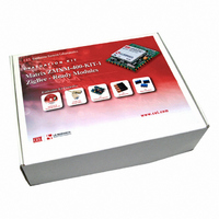
ZMXM-400-KIT-2 CEL, ZMXM-400-KIT-2 Datasheet

ZMXM-400-KIT-2
Specifications of ZMXM-400-KIT-2
101-MTX10-KIT1
ZMXM-400-KIT-1
ZMXM-400-KIT-1
ZMXM-KIT-1
ZMXM-KIT-1
Related parts for ZMXM-400-KIT-2
ZMXM-400-KIT-2 Summary of contents
Page 1
... The information in this document is subject to change without notice, please confirm data is current Document No: 0004-00-07-00-000 (Issue C) Date Published: December 4, 2009 MATRIX TRANSCEIVER MODULES ZMXM-400 Series Evaluation Kits available • 17 General Purpose I/O ports • Windows® Based Test Tools • Serial UART interface • ...
Page 2
... MATRIX MODULES ORDERING INFORMATION Part Number Order Number ZMXM-400 Series ZMXM-400-1 ZMXM-400-1C ZMXM-400-KIT-2 ZMXM-401 Series ZMXM-401-1 ZMXM-401-1C ZMXM-401-KIT-1 ABSOLUTE MAXIMUM RATINGS Rating Power Supply Voltage Voltage on Any Digital Pin RF Input Power Storage Temperature Range Note: Exceeding the maximum ratings may cause permanent damage to the module or devices. ...
Page 3
... Vdd = 3.3V, unless otherwise noted) Min Typ Max 2400 2483.5 250 115.2 115.2 128 8 50 130 -89 - 2.5 31.25 0 0.7 0.9 VDD-0.25 VDD VDD 0 0 0.25 VDD-0.25 VDD VDD ZMXM-400 Series Unit MHz kbps kbps kbps μA μA dBm dBm dBm dB % dBm dBm dBm kΩ ...
Page 4
... General Purpose Digital I/0 Port 0_1 or ADC input 1Optional on-board Red LED 23 VDD PI Power Supply Input 24 GROUND GND Ground Unused I/O pins should be left unconnected and the pin state set via the Host Protocol Digital Input DO = Digital Output AI = Analog Input AO = Analog Output Description PI = Power Input GND = Ground ZMXM-400 Series ...
Page 5
... Try to keep any plastic enclosure greater than 1 cm from the antenna in any orientation. POWER AMPLIFIER Both variants of the Matrix modules contain a Power Amplifier. The Matrix 10 mW (ZMXM-400) has a maximum Power Out of 10 mW, while the Matrix 100 mW has a maximum Power Out of 100 mW. ...
Page 6
... DIMENSIONS: ZMXM-400-1 Matrix Module 10mW Dimensions in inches. Tolerances = +/-0.005” unless otherwise noted. 0.194 PIN 1: GROUND RF Shield X3 PIN 8: GROUND 0.060 DIMENSIONS: ZMXM-400-1C Matrix Module 10mW Dimensions in inches. Tolerances = +/-0.005” unless otherwise noted. Overall Height w/MMCX Connector 0.203 J2 PIN 1: GROUND RF Shield ...
Page 7
... DIMENSIONS: ZMXM-401-1 Matrix Module 100mW Dimensions in inches. Tolerances = +/-0.005” unless otherwise noted. 0.194 PIN 1: GROUND RF Shield X3 PIN 8: GROUND 0.060 DIMENSIONS: ZMXM-401-1C Matrix Module 100mW Dimensions in inches. Tolerances = +/-0.005” unless otherwise noted. Overall Height w/MMCX Connector 0.203 J2 PIN 1: GROUND RF Shield ...
Page 8
... Typ 24 Pads 0.105 Matrix Module 100mW Minimum PCB Trace, Plane and Component Keep-Out Area, All Layers PIN 1 Recommended Host PCB Edge 0.185 ZMXM-400 Series Minimum PCB Trace, Plane & Component 0.990 Keep-Out Area, All Layers PIN 24 Recommended 0.175 Host PCB Edge ...
Page 9
... Declaration of Conformity. The CE marking must be affixed legibly and indelibly to a visible location on the user’s product. FCC Approved Antennas • Integrated PCB trace antenna • Nearson S131CL-5-RMM-2450S – A 2.4GHz Dipole antenna with a 5 inch cable and a right angle MMCX connector. ZMXM-400 Series ...
Page 10
... Heating/Relow Phase The temperature rises above the liquidus temperature of the solder paste selected. Avoid a sudden rise in temperature as any slump of the solder paste could become worse. • Limit time above liquidus temperature to 35-90 seconds. • Peak reflow temperature: 230-250ºC ZMXM-400 Series ...
Page 11
... The solvent could also damage any stickers or labels. • Ultrasonic cleaning could damage the module permanently. The best approach is to consider using a “no clean” soldering paste and eliminate the post soldering cleaning step. ZMXM-400 Series ...
Page 12
... The numerous ground pins at the module perimeter should be sufficient for optimum immunity to external RF interference. Conformal Coating Conformal coating may be necessary in certain applications. Please note that the RF shield and the sticker prevent optimum inflow of liquids or aerosols. ZMXM-400 Series ...
Page 13
... To minimize risks of damage to property or injury (including death) to persons arising from defects in CEL products, customers must incorporate sufficient safety measures in their design, such as redundancy, fire-containment and anti-failure features. ZMXM-400 Series Page N/A 1,5,7, ...


