STEVAL-IHP001V3 STMicroelectronics, STEVAL-IHP001V3 Datasheet - Page 24
STEVAL-IHP001V3
Manufacturer Part Number
STEVAL-IHP001V3
Description
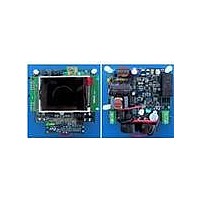
BOARD SMART PLUG STM32 SPZB260PR
Manufacturer
STMicroelectronics
Series
Zigbee™ SmartPlugr
Type
Microcontroller, Energy Meteringr
Specifications of STEVAL-IHP001V3
Frequency
2.4GHz
For Use With/related Products
STM32F10x, SPZB260-PRO, STPM01
Lead Free Status / RoHS Status
Lead free / RoHS Compliant
Other names
497-10677


Theory of operation
8.9
8.10
24/60
When a no load condition occurs (BIL=1) the integration of power is suspended and the
tamper module is disabled.
In standalone mode, if a no load condition is detected, the BIL signal blocks generation of
pulses for stepper and forces SCLNLC pin to be low. If APL = 2 (see
pin continues providing the high frequency pulses, while if APL = 3, the pulses are stopped
as happens for MOP and MON.
In peripheral mode, the BIL signal can be accessed only through the SPI interface.
Error detection
In addition to the no load condition and the line frequency band, the integration of power can
be suspended also due to detected error on the source signals.
There are two kinds of error detection circuits involved. The first checks all the ∑ Δ signals
from the analog part if any is stacked at 1 or 0 within the 1/128 of f
In case of detected error the corresponding ∑ Δ signal is replaced with an idle ∑ Δ signal,
which represents a constant value 0. All error and other resolved flags are treated as bits of
a device status and can be read out by means of SPI interface.
Another error condition occurs if the MOP, MON and LED pin outputs signals are different
from the internal signals that drive them. This can occur if some of this pin is forced to GND
or to some other imposed voltage value. In this case the internal status bit PIN is activated
providing the information that some hardware problem has been detected, for example the
stepper motor has been mechanically blocked.
Tamper detection module
The STPM01 is able to measure the current in both live and neutral wire with a time domain
multiplexing approach on a unique sigma delta modulator. This mechanism is adopted to
implement anti-tamper function. If this function is selected (see
wire currents are monitored; when the difference between the two measurements exceeds a
rated threshold the STPM01 enters the "tamper state", while in "normal state" the two
measurements are below the threshold.
In particular, both channels are not observed all the time, rather a time multiplex mechanism
is used. During the observation time of each channel, its active energy is calculated. A
tamper condition occurs when the absolute value of the difference between the two active
energy values is greater than a certain percentage of the averaged energy during the
activated tamper module (see
This percentage value can be selected between two different values (12.5 % and 6.25 %)
according to the value of the configuration bit CRIT.
The tamper condition is detected when the following formula is satisfied:
Equation 1
EnergyCH1 - EnergyCH2 > K
where K
The detection threshold is much higher than the accuracy difference of the current channels,
which should be less than 0.2 %, but, some headroom should be left for possible transition
effect, due to accidental synchronism of actual load current change with the rhythm of taking
the energy samples.
CRIT
can be 12.5 % or 6.25 %.
CRIT
Doc ID 10853 Rev 7
Equation 1:
(EnergyCH1 + EnergyCH2)/2;
).
Table
CLK
Section
9), the live and neutral
period of observation.
8.14) the LED
STPM01
Related parts for STEVAL-IHP001V3
Image
Part Number
Description
Manufacturer
Datasheet
Request
R

Part Number:
Description:
BOARD EVAL FOR MEMS SENSORS
Manufacturer:
STMicroelectronics
Datasheet:

Part Number:
Description:
KIT DEV STARTER ST10F276Z5
Manufacturer:
STMicroelectronics
Datasheet:

Part Number:
Description:
BOARD EVAL HDMI $ VIDEO SWITCH
Manufacturer:
STMicroelectronics
Datasheet:

Part Number:
Description:
BOARD DEMO ACCELEROMETER DIL24
Manufacturer:
STMicroelectronics
Datasheet:

Part Number:
Description:
BOARD STLM75/STDS75/ST72F651
Manufacturer:
STMicroelectronics
Datasheet:

Part Number:
Description:
EVAL BOARD 3AXIS MEMS ACCELLRMTR
Manufacturer:
STMicroelectronics
Datasheet:

Part Number:
Description:
BOARD EVAL 8BIT MICRO + TDE1708
Manufacturer:
STMicroelectronics
Datasheet:

Part Number:
Description:
EVAL BOARD A/D TS4657
Manufacturer:
STMicroelectronics
Datasheet:

Part Number:
Description:
BOARD ADAPTER 20DIP LIS3LV02DL
Manufacturer:
STMicroelectronics
Datasheet:

Part Number:
Description:
BOARD DEMO STM8S207R6/LIS331DLH
Manufacturer:
STMicroelectronics
Datasheet:

Part Number:
Description:
STMicroelectronics [RIPPLE-CARRY BINARY COUNTER/DIVIDERS]
Manufacturer:
STMicroelectronics
Datasheet:
Part Number:
Description:
STMicroelectronics [LIQUID-CRYSTAL DISPLAY DRIVERS]
Manufacturer:
STMicroelectronics
Datasheet:
Part Number:
Description:
BOARD EVAL FOR MEMS SENSORS
Manufacturer:
STMicroelectronics
Datasheet: