1000-TCB1C470 Silicon Laboratories Inc, 1000-TCB1C470 Datasheet - Page 9
1000-TCB1C470
Manufacturer Part Number
1000-TCB1C470
Description
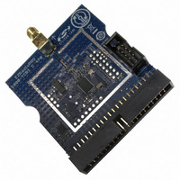
BOARD EVALUATION FOR SI1000
Manufacturer
Silicon Laboratories Inc
Type
Transceiver, ISMr
Specifications of 1000-TCB1C470
Mfg Application Notes
SI1000 Code Examples AppNote
Frequency
470MHz
Supply Voltage (min)
0.9 V
Product
RF Modules
Maximum Frequency
915 MHz
Output Power
20 dBm
Antenna
SMA
Supply Voltage (max)
3.6 V
For Use With/related Products
Si100x
Lead Free Status / RoHS Status
Lead free / RoHS Compliant
Lead Free Status / RoHS Status
Lead free / RoHS Compliant, Lead free / RoHS Compliant
Other names
336-1893


Si10xx-DK
6. Example Source Code
Example source code and register definition files are provided in the “SiLabs\MCU\Examples\Si100x\” or the
“SiLabs\MCU\Examples\Si101x\” default directory during IDE installation. These files may be used as a template
for code development. Example applications include a blinking LED example which configures the LED on the
motherboard to blink at a fixed rate.
6.1. Register Definition Files
Register definition files Si1000_defs.h and Si1010_defs.h define all SFR registers and bit-addressable control/
status bits. A macro definition header file compiler_defs.h is also included, and is required to be able to use the
Si1000 and Si1010_defs.h header file with various tool chains. These files are installed into the
“SiLabs\MCU\Examples\Si100x\Header_Files\” and “SiLabs\MCU\Examples\Si101x\Header_Files\” directories
during IDE installation by default. The register and bit names are identical to those used in the Si100x and Si101x
data sheets. These register definition files are also installed in the default search path used by the Keil Software
8051 tools. Therefore, when using the Keil 8051 tools included with the development kit (A51, C51), it is not
necessary to copy a register definition file to each project’s file directory.
6.2. Blinking LED Example
The example source files Si100x_Blinky.asm and Si101x_Blinky.c installed in the default directories
“SiLabs\MCU\Examples\Si100x\Blinky” and “SiLabs\MCU\Examples\Si101x\Blinky” show examples of several
basic MCU functions. These include disabling the watchdog timer (WDT), configuring the Port I/O crossbar,
configuring a timer for an interrupt routine, initializing the system clock, and configuring a GPIO port pin. When
compiled/assembled and linked this program flashes the LED on the Si1000 Motherboard about five times a
second using the interrupt handler with an on-chip timer.
6.3. RF Examples
The Si100x and Si101x MCUs support RF communication. Examples of RF communication using the Si100x and
Si101x products are described in Application Note AN474. The source code for the RF examples is installed into
the “SiLabs\MCU\Examples\Si100x\EZRadioPRO\” and “SiLabs\MCU\Examples\Si101x\EZRadioPRO\” during
IDE installation. The most basic example is the TxTone example. When downloaded and run on the MCU, a
915 MHz tone will be generated from the EZRadioPRO peripheral output.
Rev. 0.1
9
Related parts for 1000-TCB1C470
Image
Part Number
Description
Manufacturer
Datasheet
Request
R


Part Number:
Description:
BOARD EVALUATION FOR SI1000
Manufacturer:
Silicon Laboratories Inc
Datasheet:

Part Number:
Description:
Industrial Pressure Sensors Force Sensor 20mV/V 1000 lbf Compression
Manufacturer:
Measurement Specialties Inc.
Datasheet:

Part Number:
Description:
MODULE NETWORK 915MHZ
Manufacturer:
Helicomm Inc
Datasheet:

Part Number:
Description:
Transformers Auto 230V/115V
Manufacturer:
Stancor
Datasheet:
Part Number:
Description:
Transformers Isolation 230V/115V
Manufacturer:
Stancor
Datasheet:
Part Number:
Description:
Transformers Isolation 115V/115V
Manufacturer:
Stancor
Datasheet:

Part Number:
Description:
1000 FT SPOOL, PTFE COVERED WIRE
Manufacturer:
NEWPORT ELECTRONICS

Part Number:
Description:
1000' STRANDED CAT5E CABLE (YELLOW),ROHS
Manufacturer:
BELKIN

Part Number:
Description:
SMD/C�/SINGLE-ENDED OUTPUT SILICON OSCILLATOR
Manufacturer:
Silicon Laboratories Inc
Part Number:
Description:
Manufacturer:
Silicon Laboratories Inc
Datasheet:
Part Number:
Description:
N/A N/A/SI4010 AES KEYFOB DEMO WITH LCD RX
Manufacturer:
Silicon Laboratories Inc
Datasheet:
Part Number:
Description:
N/A N/A/SI4010 SIMPLIFIED KEY FOB DEMO WITH LED RX
Manufacturer:
Silicon Laboratories Inc
Datasheet: