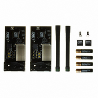
EVAL-315-LT Linx Technologies Inc, EVAL-315-LT Datasheet - Page 2

EVAL-315-LT
Manufacturer Part Number
EVAL-315-LT
Description
KIT EVAL FOR LT SERIES 315MHZ
Manufacturer
Linx Technologies Inc
Series
LTr
Type
Transceiver, Transcoderr
Datasheet
1.EVAL-418-LT.pdf
(5 pages)
Specifications of EVAL-315-LT
Frequency
315MHz
Product
RF Development Tools
Maximum Frequency
315 MHz
Supply Voltage (max)
3 V
Lead Free Status / RoHS Status
Lead free / RoHS Compliant
For Use With/related Products
LT Series RF Modules - 315MHz
Lead Free Status / Rohs Status
Lead free / RoHS Compliant
LT TRANSCEIVER EVALUATION BOARD
Page 2
1.
2.
3.
4.
5.
6.
7.
8.
9.
10. LED Button - D2
11. Buzzer Button - D3
12. LED - D0
13. Buzzer - D1
14. LED Button - D0
15. Buzzer Button - D1
16. LED - D2
17. Buzzer - D3
1
1
Battery - 3VDC
Power Switch
Prototyping Area
Breakout Header
Confirmation LED
Routing Switches
LT Series Transceiver Module
MT Series Transcoder
Reverse-Polarity SMA Antenna Connector
14
10
2
2
3
3
15
11
17
16
12
13
4
4
6
6
5
5
7
8
8
7
9
9
THEORY OF OPERATION
DEVELOPMENT USING THE PROTOTYPING AREA
The two transceiver evaluation boards are identical, but they are populated
slightly differently. The MT Series transcoder is both an encoder and a decoder,
with the input or output nature of each line being determined by how the board
is populated. One board will have buttons S0 and S1 populated, making those
lines inputs. On the other board, those lines will be connected to the buzzer and
LED, respectively. Conversely, the first board will have lines D2 and D3
connected to the buzzer and LED, while the second board has buttons S2 and
S3 populated. This allows for bi-directional remote control. To use the kit, simply
attach the antennas, turn on the power, and press one or both of the buttons on
a board. When S0 or S2 is pressed, the buzzer will sound; when S1 or S3 is
pressed, the LED will turn on.
Both boards have a confirmation LED. When one transcoder sends a command
to the second transcoder, the second transcoder will send a confirmation back to
the first transcoder indicating that the command was received and the action
performed. When the first transcoder receives the confirmation, it will turn on the
CONFIRM LED to indicate this. This feature offers the ability to range test
without needing to be in visual or hearing range of both boards.
The MT Series Transcoder Data Guide goes into the many features of the
transcoders in detail, but this is the only set-up required for operation of this kit.
In addition to their evaluation functions, the boards may also be used for actual
product development. They feature a prototyping area to facilitate the addition of
application-specific circuitry. This area has a connection to V
and ground at the top which can be used to power the added circuitry.
NOTE: If added circuitry requires a higher current, the on-board batteries must be removed
and the board powered from an external source.
The holes are plated and set at 0.100” on center with a 0.040” diameter, making
it easy to add most industry-standard SIP and DIP packages to the board.
All of the lines from the transceiver have been wired out to a row of plated holes
on the right side of the prototyping area. Four of the data lines from the
transcoder have also been wired out. This allows for easy access to connect
external circuitry to the modules and the transcoder. Three lines from the
transceiver (DATA, TR_SEL, and PDN) have been routed to switches. The
switches connect the lines to either the transcoder or the prototyping area. This
allows the transceiver to be conveniently switched between the transcoder and
application circuitry during testing.
CC
at the bottom
Page 3


