MDEV-433-HH-LR8-HS Linx Technologies Inc, MDEV-433-HH-LR8-HS Datasheet - Page 5
MDEV-433-HH-LR8-HS
Manufacturer Part Number
MDEV-433-HH-LR8-HS
Description
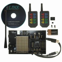
KIT DEV TX 433MHZ HS LONG-RANGE
Manufacturer
Linx Technologies Inc
Type
Transmitterr
Datasheet
1.MDEV-418-HH-LR8-HS.pdf
(9 pages)
Specifications of MDEV-433-HH-LR8-HS
Frequency
433MHz
Product
RF Development Tools
Maximum Frequency
433.92 MHz
Supply Voltage (max)
9 V
Lead Free Status / RoHS Status
Lead free / RoHS Compliant
For Use With/related Products
Linx OEM Module
Lead Free Status / Rohs Status
Lead free / RoHS Compliant


THE DECODER BOARD
Page 8
Figure 6: The Decoder Area
The Decoder Area
The decoder board has six main sections of interest: the decoder area, the RF
area, the USB area, the key exchange area, the power supply, and the
prototyping area.
The figure below shows the decoder area of the development board.
The decoder is located in the center beneath the Linx logo. To the left are LEDs
which are connected to the decoder data lines. These will light up when the
decoder receives a signal from the encoder to take the data line high. LED D0
corresponds to data line D0, and so forth.
Beneath the decoder is an LED that is connected to the MODE_IND line. This
will light up as described in the HS Series Decoder Data Guide.
Beneath the LED are three buttons. The one on the left labeled HS_SEND_KEY
is connected to the SEND_COPY line on the decoder. The one in the middle is
connected to the LEARN line, and the one on the right is connected to the
CREATE_KEY line. The HS_SEND_KEY button will cause the decoder to begin
sending a copy of its User Data when pressed at the same time as the LEARN
button. The LEARN button is used to learn the Control Permissions from the
encoder and, with the other two buttons, to make the decoder enter special
modes. The CREATE_KEY button will cause the decoder to create a new key
when pressed at the same time as the LEARN button. All of these functions are
described in detail in the HS Series Decoder Data Guide.
There is one function switch to the left of the CREATE button. BSEL0 is used to
set the baud rate of the decoder as described in Table 1.
*Important* The encoder must be set to the
same baud rate in order for the signal to be
received correctly. The HS Series Long-Range
Handheld Transmitter is set to 4,800bps, so
this switch must be in the down position.
Table 1: Baud Rate Selection Table
BSEL0
0
1
Baud Rate (bps)
28,800
4,800
THE DECODER BOARD (CONT.)
Figure 7: The Decoder Board RF Area
Figure 8: The Decoder Board USB Area
The Decoder Board RF Area
The Decoder Board USB Area
The figure below shows the RF area of the development board.
This board is populated with the LR Series receiver. The ANT1 connector is
provided for attachment of the included antenna.
The decoder development board has a Linx SDM-USB-QS-S module for use
with the included development software. This module is powered by the USB
bus, so it will not pull any current from the battery. The figure below shows the
USB area on the decoder board.
The microcontroller on the right monitors the decoder data lines and generates
commands that are sent to the development software on the PC via the QS
Series USB module. The RX_IND LED to the left of the module will flash to
indicate that data is being received from the microcontroller.
Page 9
Related parts for MDEV-433-HH-LR8-HS
Image
Part Number
Description
Manufacturer
Datasheet
Request
R

Part Number:
Description:
KIT MASTER DEV MS KEYFOB 433MHZ
Manufacturer:
Linx Technologies Inc
Datasheet:

Part Number:
Description:
KIT DEV TX 433MHZ HS COMPACT
Manufacturer:
Linx Technologies Inc
Datasheet:

Part Number:
Description:
KIT DEV TX 433MHZ MS SERIES
Manufacturer:
Linx Technologies Inc
Datasheet:

Part Number:
Description:
KIT DEV TX 433MHZ MS SER LONG-RG
Manufacturer:
Linx Technologies Inc
Datasheet:

Part Number:
Description:
RF Modules & Development Tools 1 Button MS Keyfob Dev Sys 433MHz
Manufacturer:
Linx Technologies Inc
Datasheet:
Part Number:
Description:
RF Modules & Development Tools 3 Button MS Keyfob Dev Sys 433MHz
Manufacturer:
Linx Technologies Inc
Datasheet:
Part Number:
Description:
RF Modules & Development Tools 4 Button MS Keyfob Dev Sys 433MHz
Manufacturer:
Linx Technologies Inc
Datasheet:
Part Number:
Description:
RF Modules & Development Tools 2 Button MS Keyfob Dev Sys 433MHz
Manufacturer:
Linx Technologies Inc
Datasheet:

Part Number:
Description:
RF Development Tools 1-5 Button Keyfob Dev Sys 433MHz
Manufacturer:
Linx Technologies
Datasheet:

Part Number:
Description:
HOLDER BATTERY 20MM COIN CR2032
Manufacturer:
Linx Technologies Inc
Datasheet:

Part Number:
Description:
MODULE USB LOW SPEED
Manufacturer:
Linx Technologies Inc
Datasheet:

Part Number:
Description:
IC TRANSCODER MT BI-DIR 20-SSOP
Manufacturer:
Linx Technologies Inc
Datasheet:

Part Number:
Description:
IC ENCODER LOW SECURITY 8DIP
Manufacturer:
Linx Technologies Inc
Datasheet:

Part Number:
Description:
IC DECODER MS SERIES 20-SSOP
Manufacturer:
Linx Technologies Inc
Datasheet:
Part Number:
Description:
IC ENCODER MS SERIES 20-SSOP
Manufacturer:
Linx Technologies Inc
Datasheet: