MDEV-LICAL-HS Linx Technologies Inc, MDEV-LICAL-HS Datasheet
MDEV-LICAL-HS
Specifications of MDEV-LICAL-HS
MDEV-LIC-HS


Related parts for MDEV-LICAL-HS


MDEV-LICAL-HS Summary of contents
Page 1
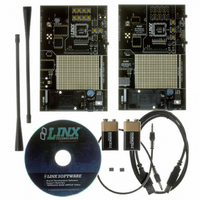
... ORDERING INFORMATION PART # DESCRIPTION MDEV-LICAL-HS HS Series Master Development System w/ LR Series MDEV-LICAL-HS-ES HS Series Master Development System w/ ES Series INTRODUCTION The HS Series encoders and decoders are ideal for remote control and command, security, keyless entry, status monitoring, and a host of similar applications. They encode the status eight buttons or contacts into a highly secure serial output intended for transmission via infrared link ...
Page 2
HS SERIES ENCODER DEVELOPMENT BOARD Figure 1: HS Series Encoder Development Board 1. 9V Battery 2. Power Jack 3. On-Off Switch 4. Voltage Regulator 5. Prototype Area 6. Break-Out Header 7. RP-SMA ...
Page 3
USING THE DEVELOPMENT BOARDS After unpacking the development system, attach an antenna to each board, install the supplied 9V battery, and turn on the power switches. The encoder and decoder will be set at the factory and will work straight ...
Page 4
THE ENCODER BOARD The encoder board has three sections that are of primary interest: the encoder area, the transmitter area, and the key exchange area. The Encoder Area The figure below shows the encoder area of the development board. Figure ...
Page 5
THE ENCODER BOARD (CONT.) VCC R15 9.1M VCC R17 9.1M R19 10k R14 VCC 5.1M U6 SW8 - + R16 IR1 C4 9.1M GND 4.7uF GND GND GND GND GND Figure 7: The Infrared Receiver Circuit The left side of ...
Page 6
THE DECODER BOARD (CONT.) The Decoder Board RF Area The figure below shows the RF area of the development board. Figure 9: The Decoder Board RF Area This board can be populated with either the LR Series receiver (as shown) ...
Page 7
INSTALLING THE SOFTWARE AND DRIVERS The software included with the Master Development System uses the QS Series Direct Drivers and cannot be used with the Virtual COM Port Drivers. For this reason, only the Direct Drivers are included on the ...
Page 8
Page 14 POWER SUPPLY SECTION J1 Va SW15 SW Vb VREG-3V Vb PWRJACK POWER SWITCH VREG-5V (ES RX ONLY) VCC 2 U2 Vout DIODE400 220uF 9V BATTERY GND GND GND GND USB SECTION J2 USB-B 4 ...
Page 9
WIRELESS MADE SIMPLE U.S. CORPORATE HEADQUARTERS LINX TECHNOLOGIES, INC. 159 ORT LANE MERLIN, OR 97532 PHONE: (541) 471-6256 FAX: (541) 471-6251 www.linxtechnologies.com Disclaimer Linx Technologies is continually striving to improve the quality and function of its products. For this ...