ZFSM-101-KIT-1 CEL, ZFSM-101-KIT-1 Datasheet
ZFSM-101-KIT-1
Specifications of ZFSM-101-KIT-1


Related parts for ZFSM-101-KIT-1


ZFSM-101-KIT-1 Summary of contents
Page 1
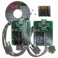
... Integrated Transceiver Module for ZigBee/IEEE 802.15.4 Evaluation Kit available; part number ZFSM-101-KIT-1 DESCRIPTION The FreeStar is a miniature, fully-integrated, drop-in RF transmission solution that’s ideal for ZigBee and other low cost, low power IEEE 802.15.4 RF transmission applications. FreeStar incorporates the MC13192 transceiver IC and MC9S08GT60 microprocessor from Freescale™ ...
Page 2
... Power Supply Voltage (Vdd) Input Frequency Ambient Temperature Range Logic Input Low Voltage Logic Input High Voltage Value Unit 3.6 Vdc +10 dBm -55 to 125 ºC Min Typ Max Unit 2.4 3.3 3.6 Vdc 2405 2480 MHz - ºC 0 30% Vdd V 70% Vdd Vdd V ZFSM-100 Series ...
Page 3
... V, Temperature = 25°C unless otherwise noted) dd Min Typ Max 2400 2483.5 10 100 -92 250 19.2 2.4 3.6 125 150 42 45 < 5 80% Vdd Vdd 0 20% Vdd 2.5 -92 31.25 -92 - 250 0.8 -3.1 ZFSM-100 Series Unit MHz mW dBm kbps dBm dBm dBm dBm dBm dBm dBm dBm dB % kbps dBi dBi ...
Page 4
PIN DEFINITIONS SIGNAL PIN TYPE NAME ANT2 AO/AI ANT2 TPRF1 AO/AI TPRF1 1 GND GND 2 GND GND 3 GND GND 4 GND GND 5 DI/DO PTD3 6 DI/DO PTD4 7 AI PTB0 8 AI PTB1 9 PI VCC 10 ...
Page 5
CONNECTOR LEGEND TYPE DEFINITION DI DIGITAL INPUT DO DIGITAL OUTPUT AI ANALOG INPUT AO ANALOG OUTPUT PI POWER INPUT GND GROUND LOGIC INPUT HIGH 0 < V < LOGIC INPUT LOW 0 < V < ...
Page 6
RADIATION PATTERNS FreeStar Rev B 2440 MHz Device Orientation Polarization (V) vertical (V) horizontal (H) vertical (H) horizontal (F) vertical (F) horizontal Toatal Avg. Gain (dB) Gain (dB) Max Avg 0.60 -1.72 -7.27 -12.37 -4.00 -10.91 0.02 -5.90 -6.62 -13.52 ...
Page 7
TYPICAL PERFORMANCE / CURVES Typical Output power versus MC13192 power setting (Vdd 3.3V, 25°C) Power Setting Output Power > dBm 28 19.6 dBm 26 18.3 dBm 24 18 dBm 22 17.6 dBm 20 17 dBm 18 11.4 ...
Page 8
Typical Output Spectrum of Transmitter Receive Port Input Impedance at Antenna ...
Page 9
EXAMPLE INTERFACE DIAGRAMS Sample Connection Diagram when Using Serial Interface DI/DO PTD3 DI/DO PTD4 FreeStar RF Module AI PTB1 AI PTB0 Sample ...
Page 10
MECHANICAL DRAWINGS Assembly Drawing with PIN Nomenclature Module – Dimensions and Keepouts PCB FOOTPRINT ...