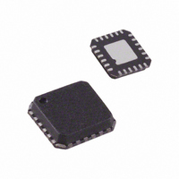
ADL5375-05ACPZ-R7 Analog Devices Inc, ADL5375-05ACPZ-R7 Datasheet - Page 2

ADL5375-05ACPZ-R7
Manufacturer Part Number
ADL5375-05ACPZ-R7
Description
IC MOD QUAD 400MHZ-6GHZ 24LFCSP
Manufacturer
Analog Devices Inc
Datasheet
1.ADL5375-05ACPZ-R7.pdf
(32 pages)
Specifications of ADL5375-05ACPZ-R7
Design Resources
Interfacing ADL5375 to AD9779A Dual-Channel, 1 GSPS High Speed DAC (CN0021) Broadband Low EVM Direct Conversion Transmitter (CN0134)
Function
Modulator
Lo Frequency
400MHz ~ 6GHz
Rf Frequency
400MHz ~ 6GHz
P1db
10.4dBm
Noise Floor
-157.6dBm/Hz
Output Power
1.71dBm
Current - Supply
200mA
Voltage - Supply
4.75 V ~ 5.25 V
Test Frequency
3.5GHz
Package / Case
24-VFQFN, 24-CSP Exposed Pad
Frequency Range
400MHz To 6GHz
Rf Type
Quadrature
Supply Voltage Range
4.75V To 5.25V
Rf Ic Case Style
LFCSP
No. Of Pins
24
Operating Temperature Range
-40°C To +85°C
Frequency Max
6GHz
Lead Free Status / RoHS Status
Lead free / RoHS Compliant
Other names
ADL5375-05ACPZ-R7TR
Available stocks
Company
Part Number
Manufacturer
Quantity
Price
Part Number:
ADL5375-05ACPZ-R7
Manufacturer:
ADI/亚德诺
Quantity:
20 000
ADL5375
TABLE OF CONTENTS
Features .............................................................................................. 1
Applications ....................................................................................... 1
Functional Block Diagram .............................................................. 1
General Description ......................................................................... 1
Revision History ............................................................................... 2
Specifications ..................................................................................... 3
Absolute Maximum Ratings ............................................................ 7
Pin Configuration and Function Descriptions ............................. 8
Typical Performance Characteristics ............................................. 9
Theory of Operation ...................................................................... 19
Basic Connections .......................................................................... 20
REVISION HISTORY
11/08—Rev. 0 to Rev. A
Change AD9779 to AD9779A .......................................... Universal
Added Endnote, I/Q Input Bias Level and Absolute
Voltage Level Parameters, Table 1 .................................................. 6
Added Absolute Voltage Level Parameter, Table 1 ....................... 6
12/07—Revision 0: Initial Version
ESD Caution .................................................................................. 7
ADL5375-05 .................................................................................. 9
ADL5375-15 ................................................................................ 14
Circuit Description..................................................................... 19
Power Supply and Grounding ................................................... 20
Baseband Inputs .......................................................................... 20
LO Input ...................................................................................... 20
Rev. A | Page 2 of 32
Optimization ................................................................................... 22
Applications Information .............................................................. 23
Evaluation Board ............................................................................ 27
Characterization Setup .................................................................. 29
Outline Dimensions ....................................................................... 31
RF Output .................................................................................... 20
Output Disable ............................................................................ 21
DAC Modulator Interfacing ..................................................... 23
Using the AD9779A Auxiliary DAC for Carrier Feedthrough
Nulling ......................................................................................... 24
GSM/EDGE Operation ............................................................. 25
W-CDMA Operation ................................................................. 25
LO Generation Using PLLs ....................................................... 26
Transmit DAC Options ............................................................. 26
Modulator/Demodulator Options ........................................... 26
Thermal Grounding and Evaluation Board Layout ............... 28
Ordering Guide .......................................................................... 31


