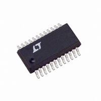
LT5500EGN Linear Technology, LT5500EGN Datasheet

LT5500EGN
Specifications of LT5500EGN
Available stocks
Related parts for LT5500EGN
LT5500EGN Summary of contents
Page 1
... IIP3 of + 8dBm at 2.5GHz. The mixer has 5dB of conversion gain and an IIP3 of – 2.5dBm at 2.5GHz, with –10dBm LO input power. , LTC and LT are registered trademarks of Linear Technology Corporation. All other trademarks are the property of their respective owners. GAIN SELECT ...
Page 2
... CONDITIONS Terminated 50Ω Source No External Matching With External Matching Two Tone Test, ∆f = 2MHz Two Tone Test, ∆f = 2MHz Terminated 50Ω Source Two Tone Test, ∆f = 2MHz U W ORDER PART TOP VIEW NUMBER GND LT5500EGN 22 LNA_OUT GND – GND 15 MIX_IN ...
Page 3
ELECTRICAL CHARACTERISTICS LNA 1.8GHz, Mixer 1.8GHz, f LNA_IN MIX_IN SYMBOL PARAMETER LO Frequency Range (Note 4) IF Frequency Range (Note 3) LO-IF Isolation LO-RF Isolation RF-LO Isolation (Test circuit shown in Figure 3 for 2.5GHz application) ...
Page 4
LT5500 W U TYPICAL PERFOR A CE CHARACTERISTICS LNA Gain vs Supply Voltage and Temperature (High Gain Mode) 20 –40°C, 1.8GHz 19 25°C, 1.8GHz 18 85°C, 1.8GHz 25°C, 2.5GHz –40°C, 2.5GHz 14 85°C, 2.5GHz 13 12 3.5 ...
Page 5
W U TYPICAL PERFOR A CE CHARACTERISTICS Mixer Conversion Gain vs LO Power 9 8 1.8GHz 7 6 2.5GHz 280MHz 25° –5 –10 –15 ...
Page 6
LT5500 PIN FUNCTIONS EN (Pin 1): Enable Pin. A voltage less than 0.3V (Logic Low) disables the part. An input greater than 1.35V (Logic High) enables the part. This pin should be bypassed to ground with a ...
Page 7
W BLOCK DIAGRA 4, 11, 14, 16, 20 APPLICATIONS INFORMATION The LT5500 consists of an LNA, a Mixer buffer and the associated bias circuitry. The chip is designed to be compatible with IEEE802.11b wireless local ...
Page 8
LT5500 U U APPLICATIONS INFORMATION APPLICATION DEPENDENT COMPONENT VALUES RF INPUT 1.8GHz 2.5GHz L4 4.7nH 2.7nH L2 12nH 4.7nH L3 4.7nH 1.8nH C4 220pF 220pF C17 10pF 10pF L9 5.6nH 2.7nH C23 1.8pF 1.5pF 280MHz IF OUTPUT L7 15nH T1 ...
Page 9
U U APPLICATIONS INFORMATION Modes of Operation The LT5500 has three operating modes: 1. Shutdown 2. LNA High Gain 3. LNA Low Gain For shutdown, the EN pin and the GS pin must be at logic Low. Logic Low is ...
Page 10
LT5500 U U APPLICATIONS INFORMATION E1 V CC1 1µ 100pF R3 0Ω R4 0Ω J2 LNA_IN C6 1µF C9 100pF L5 4.7nH CC2 5.1k SW1 C24 5. 100pF ...
Page 11
... Figure 11. Bottom Side Silkscreen of Evaluation Board Information furnished by Linear Technology Corporation is believed to be accurate and reliable. However, no responsibility is assumed for its use. Linear Technology Corporation makes no represen- tation that the interconnection of its circuits as described herein will not infringe on existing patent rights. ...
Page 12
... Direct Conversion Quadrature Demodulator 21.5dBm IIP3,Integrated LO Quadrature Generator LT5522 600MHz to 2.7GHz High Signal Level Mixer LTC5532 300MHz to 7GHz Precision RF Power Detector ThinSOT is a trademark of Linear Technology Corporation. Linear Technology Corporation 12 1630 McCarthy Blvd., Milpitas, CA 95035-7417 (408) 432-1900 FAX: (408) 434-0507 ● ...


