AWA24S Artaflex Inc, AWA24S Datasheet - Page 3
AWA24S
Manufacturer Part Number
AWA24S
Description
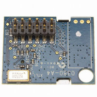
MODULE POWER AMPLIFIER
Manufacturer
Artaflex Inc
Series
WirelessUSB™r
Datasheet
1.AWA24S.pdf
(15 pages)
Specifications of AWA24S
Frequency
2.4GHz
Data Rate - Maximum
1Mbps
Modulation Or Protocol
DSSS, GFSK
Applications
Wireless Modules
Power - Output
-5dBm ~ 20dBm
Sensitivity
-93dBm
Voltage - Supply
2.5 V ~ 3.6 V
Current - Receiving
23mA
Current - Transmitting
195mA
Data Interface
Connector, 2 x 6 Header, 2mm Pitch
Antenna Connector
On-Board, Chip
Operating Temperature
0°C ~ 70°C
Package / Case
Module
Lead Free Status / RoHS Status
Lead free / RoHS Compliant
Memory Size
-
Other names
748-1003
Available stocks
Company
Part Number
Manufacturer
Quantity
Price
Company:

Part Number:
AWA24S
Manufacturer:
Artaflex Inc
Quantity:
135


4.3
AWA24S does not support ATS due to inherent hardware limitations. A firmware based ATS scheme can be implemented instead
to get the same functionality.
4.4
By combining the DATA_CODE_ADR code lengths and data transmission modes described above, the AWA24S supports the
following modes and data rates.
Table 1 - Data Rates
5
The AWA24S has an SPI interface supporting communications between an application MCU and one or more slave devices
(including the AWA24S). The SPI interface supports single-byte and multi-byte serial transfers using either 4-pin or 3-pin
interfacing. The SPI communications interface consists of Slave Select (
(MOSI), Master In-Slave Out (MISO), or Serial Data (SDAT).
The SPI communications is as follows:
The device receives SCK from an application MCU on the SCK pin. Data from the application MCU is shifted in on the MOSI
pin. Data to the application MCU is shifted out on the MISO pin. The active-low Slave Select (
initiate an SPI transfer.
The application MCU can initiate SPI data transfers via a multi byte transaction. The first byte is the Command/Address byte,
and the following bytes are the data bytes as shown in Figure 2 through Figure 5.
The SPI communications interface has a burst mechanism, where the first byte can be followed by as many data bytes as
desired. A burst transaction is terminated by de-asserting the slave select (
The SPI communications interface single read and burst read sequences are shown in Figure 3 and Figure 4, respectively.
The SPI communications interface single write and burst write sequences are shown in Figure 5 and Figure 6, respectively.
This interface may optionally be operated in a 3-pin mode with the MISO and MOSI functions combined in a single
bidirectional data pin (SDAT). When using 3-pin mode, user firmware should ensure that the MOSI pin on the MCU is in a
high impedance state except when MOSI is actively transmitting data.
Artaflex Inc.
Markham, Ontario, Canada
L3R8T9
905-479-0148
215 Konrad Crescent
GFSK
32-Chip 8DR
64-chip 8DR
32-chip DDR
64-chip DDR
64-chip SDR
Auto Transaction Sequencer (ATS)
Data Rates
SPI Communication
Command Direction (bit 7) = “1” enables SPI write transaction. A “0” enables SPI read transactions.
Command Increment (bit 6) = “1” enables SPI auto address increment. When set, the address field automatically
increments at the end of each data byte in a burst access, otherwise the same address is accessed.
Six bits of address.
Eight bits of data.
RF Transmission Mode
[2]
[2,3]
[3]
[3]
2.4GHz Radio Module with Integrated Power Amplifier
Page 3 of 15
Raw Data Rate kbps
1,000.00
250.00
125.00
62.50
31.25
15.63
)
, Serial Clock (SCK), and Master Out- Slave In
= 1).
http://www.artaflexmodules.com
) pin must be asserted to
Revised October 6, 2008
DSAWA24S Rev 2v6
Data Sheet
AWA24S
Related parts for AWA24S
Image
Part Number
Description
Manufacturer
Datasheet
Request
R


