ETRX2-PA Telegesis Ltd, ETRX2-PA Datasheet
ETRX2-PA
Specifications of ETRX2-PA


Related parts for ETRX2-PA


ETRX2-PA Summary of contents
Page 1
... Telegesis ETRX2-PA, ETRX2HR-PA ETRX2-PA and ETRX2HR-PA ZIGBEE® MODULES ©2009 Telegesis (UK) Ltd PRODUCT MANUAL ETRX2PA Product Manual (Rev 1.07) TG-ETRX2PA-PM-003-107 Product Manual 1.07 ...
Page 2
... PHYSICAL DIMENSIONS .................................................................................................. 21 13 SOLDERING TEMPERATURE TIME PROFILE (FOR REFLOW SOLDERING) .............. 23 13.1 For Leaded Solder ........................................................................................................... 23 13.2 For Lead-free Solder........................................................................................................ 23 14 PRODUCT LABEL DRAWING ........................................................................................... 24 15 RECOMMENDED FOOTPRINT ......................................................................................... 25 15.1 Example carrier board...................................................................................................... 26 16 RELIABILITY TESTS ......................................................................................................... 27 ©2009 Telegesis (UK) Ltd Table of Contents - 2 - ETRX2PA Product Manual (Rev 1.06) ETRX2PA ...
Page 3
... Component Orientation.................................................................................................... 30 18.3 Reel Dimensions.............................................................................................................. 30 18.4 Packaging ........................................................................................................................ 30 19 ORDERING INFORMATION .............................................................................................. 31 20 TRADEMARKS................................................................................................................... 32 21 DISCLAIMER...................................................................................................................... 32 22 ROHS DECLARATION....................................................................................................... 32 23 DATA SHEET STATUS...................................................................................................... 32 24 LIFE SUPPORT POLICY.................................................................................................... 32 25 RELATED DOCUMENTS ................................................................................................... 33 26 CONTACT INFORMATION ................................................................................................ 33 ©2009 Telegesis (UK) Ltd - 3 - ETRX2PA Product Manual (Rev 1.06) ETRX2PA ...
Page 4
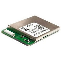
... Ember EM250 single chip ZigBee®/IEEE802.15.4 solution. It has been designed to be integrated into any device without the need for RF experience and expertise. The form factor of the ETRX2-PA is identical to the ETRX2, so either module can be used depending on the range requirements of the particular ...
Page 5
... The configurable functionality often allows the ETRX2-PA wireless meshing module to be used without an additional host microcontroller saving even more integration time and costs. In addition to the Telegesis AT Commandset, the ETRX2-PA can be used in with custom build firmware or the Ember EZSP over UART protocol interface... ...
Page 6
... Unexpected start-up in bootloader mode The bootloader which runs on the ETRX2-PA can be initiated with a firmware command, but it can also be triggered in hardware. If the A/D2 input (pad 10) is pulled low during the boot-up of the module it will enter the bootloader routine, so exercise caution when doing hardware design and ensure that this pin is not grounded during start-up and reset or driven from an analogue voltage that may be sensed as a logic 0 ...
Page 7
... R&TTE Directive. The final product must not exceed the specified power ratings, antenna specifications and installation requirements as specified in this ETRX2-PA user manual. If any of these specifications are exceeded in the final product then a submission must be made to a notified body for compliance testing to all of the required standards. ...
Page 8
... Declarations of Conformity Telegesis (UK) Ltd has issued Declarations of Conformity for the ETRX2-PA ZigBee® RF Modules, which cover Radio Emissions, EMC and Safety. These documents are available from our website or on request 2.4 IEEE 802.15.4 IEEE 802.15 standard for low data rate, wireless networks (raw bit-rate within a radio packet of 250kbps @2.4GHz) which focuses on low cost, low duty cycle, long primary battery life applications as well as mains-powered applications the basis for the open ZigBee® ...
Page 9
... The table below gives details about the 38 module pin signals for direct SMD soldering of the ETRX2-PA to the application board. The pin numbers shown in brackets () are the related pins of the EM250. In order to use the ETRX2- plug-in solution a Harwin 1.27mm pitch connector can be fitted on the bottom of the ETRX2-PA (Harwin part number M50-3601042) ...
Page 10
... TXD GPIO 9 (32) RXD GPIO 10 (33) GND GND I/O10 GPIO 15 (41) I/O11 GPIO 16 (40) GND GND VCONT {2} n/a GND GND GND GND GND GND GND GND N/C {4} GPIO 7 (30) Table 2. Pin Information - 10 - ETRX2 Harwin Pin ETRX2PA Product Manual (Rev 1.07) ETRX2PA ...
Page 11
... Telegesis (UK) Ltd VREG VBAT EM250 LDO 1,8Vdc RF transceiver 2.4GHz BALUN Tx 16-bit XAP16b uC 128kB flash / 5k RAM BALUN Rx 24MHz Figure 2: Hardware Diagram Depending on the power supply conditions of the application the - 11 - GPIO0 GPIO16 RESET 4 SIF 32,768kHz (optional) ETRX2PA Product Manual (Rev 1.07) ETRX2PA RESET programming ...
Page 12
... I/O. UART The AT style command interpreter can be accessed via the TXD and RXD pins. The ETRX2-PA can buffer up to 128 bytes of incoming data in a software FIFO buffer and uses XON/XOFF or hardware flow control. See [2] for more information about the built-in UART. ...
Page 13
... Telegesis user guide. Check www.telegesis.com for updates. Each module comes with a unique 64-bit 802.15.4 identifier which is stored in non-volatile memory. The commands and responses pass through the serial port of the ETRX2-PA as ASCII text simple terminal application will usually suffice. We provide Telegesis Terminal but it is not an essential feature. ...
Page 14
... Software Interface Using the default firmware the ETRX2-PA is controlled using a simple AT-style command interface and (mostly) non-volatile S-Registers. Commands, please refer to the AT command dictionary document which corresponds to the firmware revision you intend to use. In addition to the command dictionary there are user guides explaining the features of the firmware in more detail. If you need to find out which firmware resides on your module simply type “ ...
Page 15
... Operating Conditions Please Note: The firmware of the ETRX2 series and the ETRX2-PA series is identical, therefore when talking about power settings in the following chapters, the actual output power out of the on board EM250 is described, rather than the power amplified output out of the module. For the relationship between EM250 power settings and module output power please relate to chapter 11 ...
Page 16
... VA/D f SPI T op Table 4. Operating Conditions - 16 - Value Min Typ Max 2.7 3.3 3.5 Vdc 2405 2480 MHz 0 dBm -43 +3 dBm -43 -3 dBm -43 -14 dBm -22 +17.5 dBm -21 +18 0. VBAT 0.8x VBAT V VBAT 1 MHz -40 +85 °C ETRX2PA Product Manual (Rev 1.07) ETRX2PA Unit ...
Page 17
... OH I OHS I OLS I OHH I OLH Table 5. DC Electrical Characteristics mainly feeds circuitry on ETRX2-PA, the V REG . V is not available in Power Mode 3 (see the AT REG REG is connected to the regulator option output instead and the REG - 17 - Value Min Typ Max 3.3 3.5 1.8 1 ...
Page 18
... Spurious Emissions >1GHz ©2009 Telegesis (UK) Ltd refer to datasheet EM250 part 5.5 ADC Module refer to datasheet EM250 part 5.5 ADC Module 1.2V 1.2V Table 6. A/D Converter Characteristics -92 - -80 - ETRX2PA Product Manual (Rev 1.07) ETRX2PA Value Unit Min Typ Max -96 - dBm -97 - dBm 4 - dBm 30 ...
Page 19
... Table 10. Power On Reset Specifications for EM250 chip ©2009 Telegesis (UK) Ltd 14 15 -40 -20 - Table 7. AC Electrical Characteristics - - Table 8. Standby Spurious Emissions Table 9. Synthesiser Characteristics 1.0 0.5 1.35 0. ETRX2PA Product Manual (Rev 1.07) ETRX2PA Value Unit Min Typ Max 17.5 20 dBm 18.5 0 dBm -22 dBm ppm -36 ...
Page 20
... Please Note: The power setting is the setting of the EM250’s output power (before amplification). This setting is used by all firmware running on the ETRX2-PA. ©2009 Telegesis (UK) Ltd Output power vs power setting -30 -20 -10 power setting dBm Figure 3. Output Power vs. Power Setting Module current vs power set t ing ...
Page 21
... Pitch Y2 Distance between rows of pads Y3 Distance between edge of PCB and pad Y4 Distance between edge of PCB and pad ©2009 Telegesis (UK) Ltd Figure 5: ETRX2-PA Physical Dimensions Explanation Table 11. Physical Dimensions ETRX2- ETRX2PA Product Manual (Rev 1.07) ETRX2PA Distance 37.5mm 20.5mm 3.20mm 2.54mm 2.24mm 3 ...
Page 22
... If using the U.FL RF connector the “keep- out” area can be significantly reduced. strongly on the antenna used and also the housing of the finished product. ©2009 Telegesis (UK) Ltd NB : The module transmit/receive range will depend - 22 - ETRX2PA Product Manual (Rev 1.07) ETRX2PA ...
Page 23
... Telegesis (UK) Ltd 235°C max. 220 ±5°C 200°C 90 ±30s Figure 6: Temperature Profile for Lead Solder 220°C 90 ±30s - ±1s 30 +20/-10s Time [s] 30 +20/-10s Time [s] ETRX2PA Product Manual (Rev 1.07) ETRX2PA ...
Page 24
... Year-Month-Day [6 signs], separated by a semicolon. ©2009 Telegesis (UK) Ltd Figure 8: Product Label Description Table 12. ETRX2-PA Label Details - 24 - ETRX2PA Product Manual (Rev 1.07) ETRX2PA ...
Page 25
... You must also ensure that there are no exposed pads or vias on your layout which may contact with the pads (for the optional connector), or vias on the bottom surface of the ETRX2-PA module. If the module soldered by hand for prototyping we recommend that you increase the height of the pads to allow easier access ...
Page 26
... Finally to provide a good reference ground to the on board antenna, the carrier board should have a ground plane spanning no less than 60 x 50mm. In many cases a smaller ground plane will suffice, but a degradation in radio performance could be the result. ©2009 Telegesis (UK) Ltd Figure 10: Reference Board - 26 - ETRX2PA Product Manual (Rev 1.07) ETRX2PA ...
Page 27
... RH, 300h the same as the above -40°C, 300h the same as the above +85°C, 300h Table 13. Reliability Tests - 27 - ETRX2PA Product Manual (Rev 1.07) ETRX2PA Condition ...
Page 28
... Storage (before assembly of the end product) of the modules for more than one year after the date of delivery at your company even if all the above conditions (1) to (3) have been met, should be avoided. ©2009 Telegesis (UK) Ltd - 28 - ETRX2PA Product Manual (Rev 1.07) ETRX2PA ...
Page 29
... NB: Empty pockets in the component packed area shall be less than two per reel and those empty pockets shall not be consecutive. ©2009 Telegesis (UK) Ltd Force direction Speed = 300mm/min. θ= 10deg Cover tape reel strength Components Empty pockets Top cover - 29 - ETRX2PA Product Manual (Rev 1.07) ETRX2PA =0.098~0.68N (10~70g) Direction of g ...
Page 30
... Figure 2 18.4 Packaging (6) Each reel will be packed in a hermetically-sealed bag (7) Marking : Part No. / Quantity / Lot No. and manufacturer part# with bar-code ©2009 Telegesis (UK) Ltd (top view) 2 +/-0.5 Marking ? φ 330 - 30 - ETRX2PA Product Manual (Rev 1.07) ETRX2PA Component Orientation 33.5 +/-1.0 2.0 +/-0.2 ...
Page 31
... Customers’ PO’s must state the Ordering/Product Code. • There is no “blank” version of the ETRX2-PA Module available. All Modules are pre- programmed with the Telegesis AT style command interpreter based on the EmberZNet stack. (Where customers wish to add their own firmware they can erase and write it to the flash memory of the EM250). • ...
Page 32
... Customers using or selling these products for use in such applications their own risk and agree to fully indemnify Telegesis (UK) Ltd. for any damages resulting. ©2009 Telegesis (UK) Ltd - 32 - ETRX2PA Product Manual (Rev 1.07) ETRX2PA ...
Page 33
... The ZigBee® specification 26 Contact Information Website: www.telegesis.com E-mail sales@telegesis.com Telegesis (UK) Limited 3, Abbey Barn Business Centre Abbey Barn Lane High Wycombe Bucks HP10 9QQ UK Tel: +44 (0)1494 510199 Fax: +44 (0)5603 436999 ©2009 Telegesis (UK) Ltd (www.ember.com) (www.johansontechnology.com) (www.zigbee.org ETRX2PA Product Manual (Rev 1.07) ETRX2PA ...